MXFP8 GEMM: Up to 99% of cuBLAS performance using CUDA + PTX
I recently did a deep-dive on writing GEMM kernels with just CUDA + PTX for Ampere, Hopper, and Blackwell GPUs, culminating in a MXFP8 GEMM kernel which achieves up to 99% of cuBLAS (torch._scaled_mm) depending on the problem shape - see microbenchmarks below, measured with:
- B200 GPU, 1000W power
- CUDA 13.0
- PyTorch version: 2.11.0+cu130
- K-major input operands, with float32 output
| Matrix Size (M×K×N) | Custom Kernel | torch._scaled_mm (cuBLAS) | Speedup |
|---|---|---|---|
| 2048×2048×2048 | 986.90 TFLOPS | 996.05 TFLOPS | 0.99x |
| 4096×4096×4096 | 2200.29 TFLOPS | 2538.40 TFLOPS | 0.87x |
| 8192×8192×8192 | 2599.07 TFLOPS | 2691.93 TFLOPS | 0.97x |
| 16384×16384×16384 | 2487.72 TFLOPS | 2571.48 TFLOPS | 0.97x |
It was an interesting and rewarding journey, and in this post I’ll walk through some of the optimizations I did to improve from my first attempt (35% of cuBLAS) to the final design, what I tried that didn’t work (we should report failures as well!), and remaining unsolved problems (notably, M=N=K=4096 is stubbornly farther from optimal than other shapes!).
For background conext, I highly recommend reading GEMM kernel design for Ampere (Simon’s blog), Hopper (Pranjal’s blog), and Blackwell (Thien’s blog). These posts cover higher precision dtypes (float32 or bfloat16), so my goal here is to contribute a post on MXFP8 GEMM kernel design, which is a new low precision numerical format with native acceleration on Blackwell GPUs, offering up to 2x higher TFLOPs/sec than bfloat16 (theoretical).
Using MXFP8 introduces some new concepts and challenges, and those are what this post will focus on. In addition, we make heavy use of inline PTX, which is necessary to use the latest hardware features from CUDA, so I will attempt to explain the instruction requirements and semantics in plain language, hopefully more clearly than the PTX docs!
The code can be found here (kernels for Ampere and Hopper can be found in this repo as well, if you’re interested).
We’ll start with some optional background on MXFP8, walk through an illustrated overview of the initial kernel design and PTX instructions, then iteratively optimize to reach (almost) cuBLAS performance!
Table of Contents:
- (Optional background on MXFP8): What is MXFP8 and why do we care about writing a GEMM with it?
- Notation
- Block scaled tcgen05.mma requirements
- Initial kernel
- Optimization 1: Increasing MMA_N to 256, overlapping 128 columns of TMEM accumulator buffers and ping-pong between them
- Optimization 2: Increase width of vectorized stores to 8 floats via inline PTX
- Optimization 3: Increasing BK to 256
- Optimization 4: TMA multicast SFB to both CTAs
- Optimization 5: Avoid warp stalling caused by dynamic indexing into arrays
- Optimization 6: Use Hilbert curve for block scheduling to improve cache utilization
- Optimization 7: Use L1::no_allocate modifier global stores
- Optimization 8: Use Hilbert curve only for M/N/K >= 8192
- Optimization 9: New DeepGEMM inspired epilogue strategy: TMEM -> REG -> pipelined TMA stores with manual swizzle in SMEM
- Optimization 10: Heuristic based epilogue strategy
- Optimization 11: More granular TMEM overlapping
- Conclusion
(Optional background on MXFP8): What is MXFP8 and why do we care about writing a GEMM with it?
MXFP8 is a “micro-scaled” numerical format (OCP spec) defined by two parts: the data and the scales. The data is in float8 e4m3 format (1 sign bit, 4 exponent bits, 3 mantissa bits). The scales are in float8 e8m0 format (unsigned, 8 exponent bits, no mantissa bits). This is an unsigned representation of a standard float32 exponent where exponent bits are interpreted as 2^exponent, meaning these are power of 2 scales. MXFP8 uses granular 1x32 scaling factors, meaning every 1x32 chunk of input data shares a single e8m0 scale factor that is used to scale the values into the dynamic range of float8 e4m3: [-448, 448].
Benefits of MXFP8: The performance benefits of 2x higher TFLOPs/sec vs bfloat16 on Blackwell’s 5th gen tensorcores are obvious. However, MXFP8 is also better for preserving accuracy than other common low precision scaling strategies: the fine-grained 1x32 scaling factor makes it more resilient to outliers in the data. We compute the scaling factor using the absolute maximum value in the 1x32 block, to calculate how much we need to scale it (and the rest of the block) to fit in the dynamic range of e4m3, and “fill”. If all the values are very small, the values will be “stretched” to fill the dynamic range of [-448, 448]. If there is a very large value in the data, we’ll scale the values down to fit in this range. If there is a large outlier in the data, as is often the case for input activations and gradients, this can cause some already small values to underflow to 0 when we try to scale them down beyond what is representable in e4m3. That information is now lost, we can’t dequantize a 0 back to some arbitrary value. Therefore, given we expect outliers in our data, it is best to mitigate the impact of outliers by using a granular scaling factor, so the outlier can only impact those 32 elements, not more.
Notation:
M,N,K= global input tensor dimensions forA @ B = Cwith shape(M,K) @ (K,N) = (M,N)SFA,SFB= scale factors for A and B tensorsSF_K= global scale factor K dimension, which will beK//32. M and N dims of scale factor are the same as input tensor. SFA/SFB both have the same SF_K dim, but with M or N rows respectively.BM,BN,BK= tile dimensions of A ((BM,BK)) and B ((BN,BK)) we load into shared memory.SF_BK= scale factor tile K dim, equal toBK//32. Same for SFA and SFB.MMA_M,MMA_N,MMA_K= dimensions fortcgen05.mmainstruction which does matrix-multiply accumulate operation on 5th gen tensorcores<num>B- a capital “B” (e.g.128B) like this means “bytes.”<num>b- a lowercase “b” (e.g.32b) like this means “bits.”
Block scaled tcgen05.mma requirements
Before going any further, it is important to understand the requirements of the core PTX instruction we’ll use for the block scaled matrix-multiply accumulate operation: tcgen05.mma.cta_group::2.kind::mxf8f6f4.block_scale.block32.
This will inform key parts of the design.
The PTX docs have this syntax for us:
// 2. Floating-point type with block scaling:

tcgen05.mma.cta_group.kind.block_scale{.scale_vectorsize}
                                        [d-tmem],  a-desc,  b-desc, idesc,
                                        [scale-A-tmem], [scale-B-tmem], enable-input-d;

tcgen05.mma.cta_group.kind.block_scale{.scale_vectorsize}
                                        [d-tmem], [a-tmem], b-desc, idesc,
                                        [scale-A-tmem], [scale-B-tmem], enable-input-d;

.kind = { .kind::mxf8f6f4, .kind::mxf4, .kind::mxf4nvf4 }
.cta_group      = { .cta_group::1,   .cta_group::2 }
.scale_vectorsize = { .scale_vec::1X, .scale_vec::2X, .scale_vec::4X, .block16, .block32 }
Breaking components of the instruction itself:
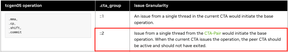
.kind= which MX dtype group/kind we’re using (in our case,mxf8f6f4covers MXFP8)..cta_group= 1 CTA or 2 CTA MMA (we will usecta_group::2to cooperatively compute a larger output tile with higher arithmetic intensity and tensorcore utilization - more on this later)scale_vectorsize=blockNvalue here defines the block size for which a single scale factor will be applied. For MXFP8, we useblock32.
Our final constructed instruction: tcgen05.mma.cta_group::2.kind::mxf8f6f4.block_scale.block32
Breaking down the instruction arguments:
[d-tmem]= TMEM accumulator base address, wrapped in brackets to dereferencea-descor[a-tmem]= For the A tile, we can either store it in SMEM and pass a SMEM descriptor, or store it in TMEM and pass the TMEM base address. The bracket notation is PTX syntax for dereferencing. (More on SMEM descriptors later).b-desc= SMEM descriptor for the B tile.idesc= instruction descriptor, which encodes things like operand dtypes, dimensions, etc. (More on this later).[scale-A-tmem]: SFA TMEM base address.[scale-B-tmem]: SFB TMEM base address.enable-input-d: set to 0 or 1, to either enable/disable accumulation (C+=A@BvsC=A@B).
We can dive into more detail later, but for now the most important things to note here are that both the accumulator AND scale factors SFA/SFB all have to live in TMEM for the MMA instruction! This constraint will shape aspects of our kernel design, since TMEM size is very limited: per SM we have 128 rows of 512 cells each (cell width is 4 bytes).
Critically, it is also important to note that the tcgen05.mma.cta_group::2.* is issued by a single thread on one CTA in the pair. This will also inform the inter-CTA synchronization patterns needed between the producer, consumer, and epilogue:
Initial kernel
We will not be starting our MXFP8 GEMM journey with an ultra-naive kernel design; having just finished working on various BF16 GEMM kernels for Blackwell, I had a pretty good idea of a sensible design to start with. Our goal here is to start with something functional, with reasonable (though not necessarily optimal) design choices that we can iterate upon.
Warp specialized persistent kernel with static schedule
We will use a standard warp-specialized producer -> consumer -> epilogue design to hide global memory latency and turn each SM into a “conveyor belt” processing tiles of computation. This design pipelines the load -> process -> store steps to overlap the expensive, high latency global loads/stores with our tcgen05.mma instructions. Ideally, our pipeline will achieve a high level of overlapping of both global loads (producer) and global stores (epilogue), and minimize tensorcore idle time. It should look something like this:
As you can see, we use a 3-stage pipeline: producer → consumer → epilogue.
- Producer: loads tiles from GMEM to SMEM
- Consumer: performs MMAs, accumulates in TMEM
- Epilogue: stores results from TMEM to GMEM
We will override the default max SMEM per CTA (48kB) to maximize the SMEM queue size per SM, and turn each SM into a “conveyor belt” hosting exactly 1 CTA that churns through blocks using the above 3 stage pipeline, hopefully achieving a high level of overlap between stages!
2CTA MMA
To maximize arithmetic intensity and tensorcore utilization, we want the M and N dimensions of our tcgen05.mma operations to be as large as possible. On Blackwell, this is achieved by using the new “2CTA MMA” feature that allows two CTAs in a thread block cluster to cooperatively compute one larger output tile. The CTA output tiles are stacked vertically; for example, with MMA_M=128 and MMA_N=256, each CTA produces a separate 128x256 tile of the 256x256 output.
Each CTA only needs to load half the A/B operands, which reduces global memory traffic and increases arithmetic intensity. Here is a diagram visualizing the tiles loaded by each CTA:

Note SFA is completely different for both CTA 0 and CTA 1, but SFB actually has to be replicated on both CTAs! Both CTAs have the full (BK//32, BN) SFB even though they each only hold (BK, BN/2) columns of B. (Fun note: this is not officially documented by NVIDIA anywhere that I’m aware of, but luckily I had seen this tweet thread from Thien about NVFP4 GEMMs prior to starting this work, and I assumed this same oddity might apply to MXFP8 as well, and so it does!)
Critically, in this design, each CTA in the pair (cluster) runs on its own SM. This is because to maximize SMEM queue depth, and thus maximize the % of time spent in the pipeline’s steady state with overlapping between global load/store latency and tensorcore MMAs, we need each CTA to allocate/own the full dynamic shared memory resources on that SM. We do this by overriding the default of 48k:
        // precompute `total_smem` = dynamic smem needed to maximize queue depth while maintaining enough room for mbarriers etc., while staying under the physical 227kb per SM limit.
        // ...
        // then override kernel dynamic shared memory limit.
        auto kernel = ws_gemm_2cta_mma<true, true, QUEUE_SIZE, BM, BN, BK, MMA_M, MMA_N, MMA_K, TMA_STORE_COLS, SWIZZLE_BYTES>;
        CUDA_CHECK(cudaFuncSetAttribute(
            kernel,
            cudaFuncAttributeMaxDynamicSharedMemorySize,
            total_smem
        ));
Starting simple with MMA_N=128
This decision is due to constraints imposed by limited TMEM width for our accumulators and SFA/SFB tiles. Per the PTX docs, the max MMA_N dimension for cta_group::2 is 256. Ideally, in efficient GEMM design we’d like to use the max MMA_N width possible AND have more than 1 MMA operation in flight at once via pipelining, to maximize our tensorcore utilization and TFLOPs/sec. How many accumulators can we hold in TMEM? With MMA_N=256 and 512 TMEM cell width we can fit exactly 2 128x256 FP32 accumulators - but will have no room left for SFA/SFB!
This design may work for BF16 GEMMs, which don’t have scale factors, SFA/SFB, but for MXFP8 this poses a problem for us.
As an side, I am actually surprised by this limitation: I would have thought NVIDIA would co-design the TMEM size with the natively accelerated low precision numerical formats to ensure we can fit at least 2 accumulators and SFA/SFB in TMEM at once.
Naively, we can either use one accumulator with MMA_N=256, or 2+ with MMA_N=128. We know from experience we want to do some kind of double-buffering to minimize gaps between MMA instructions, so let’s start with 2 accumulators using MMA_N=128 and figure out some more sophisticated strategy to make it work with MMA_N=256 later!
Understanding the synchronization patterns needed to use 2 CTA tcgen05.mma in this warp specialized paradigm is crucial for this kernel design. At a high level, the dependency chart looks like this:
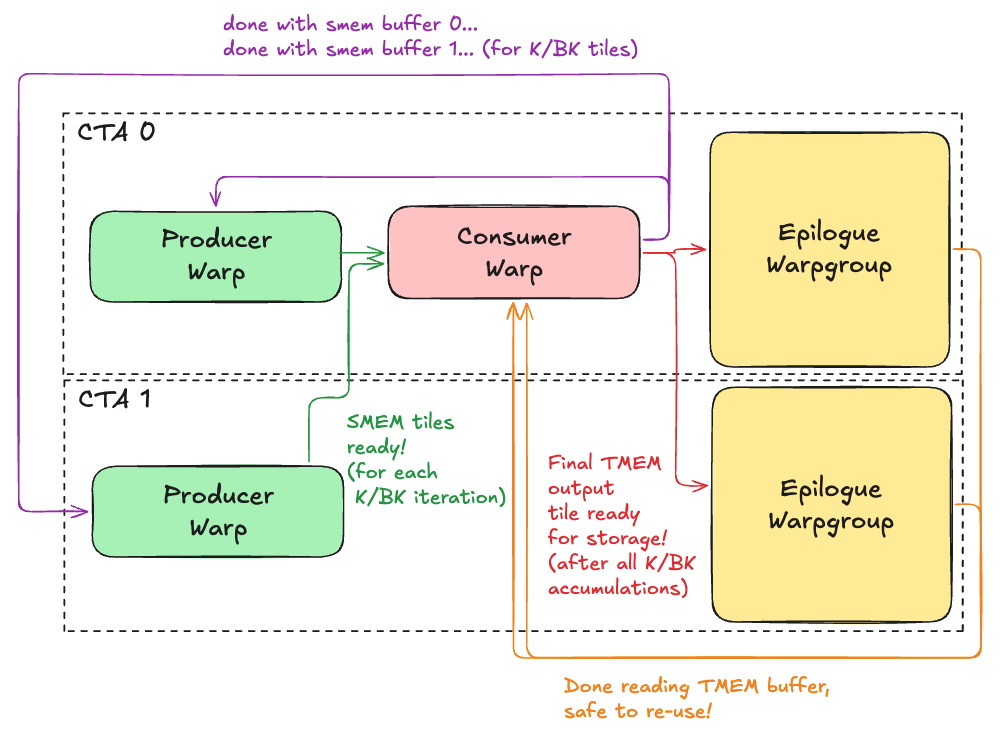
As you can see, there are complex, inter-CTA synchronization patterns to implement and use a 2CTA MMA in a warp specialized persistent GEMM kernel! We’ll break it down step by step though. First let’s dive deeper into the producer, consumer, and epilogue in turn.
Producer
We have 1 producer warp per CTA. Both CTAs will have a producer warp dedicating to loading tiles of A/B/SFA/SFB from GMEM -> SMEM with cp.async.bulk.tensor (2D+ TMA).
The high level logical flow it follows is:
- One time setup: Each CTA initializes a
smem_fullmbarrier andsmem_emptymbarrier per buffer in the queue. - On CTA 1 we map the
smem_fullmbarrier on CTA 0 before arrival by using mapa.shared::cluster.u32, which allows us to map a shared memory address to the same address on the other CTA. This is necessary because only CTA 0 will actually issue thetcgen05.mmainstruction, so we need both CTAs to signal this mbarrier when all the necessary data is ready in SMEM for the MMA.
We now enter the load loop:
- For each output tile we compute on this SM:
- For each BK chunk along the K (contracting dim we accumulate over):
try_waitloop onsmem_empty_bmar(ensure epilogue finished reading data from it).- Issue TMA load for A tile shape (BM, BK).
- Issue TMA load for B tile shape (BK, BN/2). CTA 0 loads left half of B tile, CTA 1 loads the right half.
- Issue TMA load for SFA tile shape (BM, BK//32).
- Issue TMA load for SFB tile shape (BK//32, BN).
- For each BK chunk along the K (contracting dim we accumulate over):
We will start with tile sizes BM=128, BN=128, BK=128. On each SM, our shared memory layout will look like this:
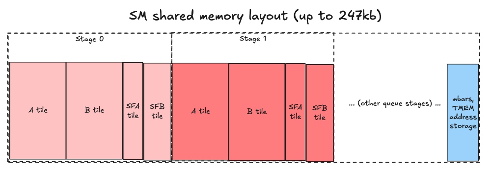
Seems simple enough, right? Well, let’s peel back another layer of the onion and see :)
Loading A/B tiles from GMEM to SMEM
Surprise - we can’t load the A/B data in simple row-major layout, as we might logically assume. To understand why, we need to first learn about “core matrices” - this was a strange concept for me to wrap my head around personally, so buckle up!
Core Matrices
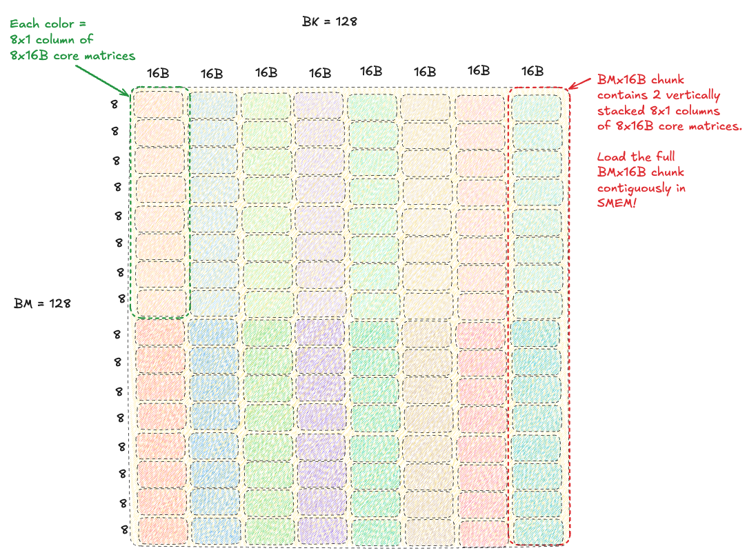
The key insight to understanding why this concept exists is that tensorcores are not actually aware of individual elements, they do not stride through data at row/column level granularity. Tensorcores only understand matrices - specifically, 8x16B “core matrices.” They view the A/B tiles as a grid of these core matrices (implies size of a systolic array or other hardware unit, physically implemented to operate on this tile size?).
Critically, each 8x16B core matrix must be contiguous in memory, and each 8x1 column of core matrices need to be contiguous in memory. To be super clear, this is 8 8x16B core matrices stacked vertically in a column, so that’s 64x16B.
Therefore, our A/B tiles must be laid out in shared memory in a way that satisfies this constraint, and we pass stride information about how to stride through this “core matrix view” of the tiles to the tcgen05.mma instruction via the shared memory descriptors (more on this later).
This means we cannot load our original row-major A/B tiles from global memory into the same layout in shared memory. We need to load into a hierarchical layout of core matrices!
Without swizzling, loading an A tile into SMEM looks like this:
Concrete example: a non-swizzled layout of core matrices in the A tensor (shape MxK, dtype float8 e4m3fn) can be represented in a tensormap for 3D TMA loads like this (pseudo-C++):
    // M,K
    // M,K/16,16
    // K/16,M,16 -> K/16 instances of M,16B strips
    uint64_t a_global_dims[3] = {16, M, K / 16};
    uint32_t a_smem_dims[3] = {16, BM, BK / 16};
    uint32_t a_strides[2] = {K, 16};
    create_3d_tensor_map(
        A,
        a_map,
        a_global_dims,
        a_smem_dims,
        a_strides
    );
Critically (do I say that too much?), the inner-most dimension of the TMA box is only 16B! With a stride between rows of 16B contiguous elements. This limits the efficacy of our global loads - doing “fatter” loads of larger chunks of contiguous data is more performant. We will see how to improve this in the next section swizzling.
You can read more about core matrices in these resources to help solidify your understanding [1, 2, 3].
In the meantime, we need to discuss how they interact with swizzling, which we will need to use to minimize shared memory write conflicts during the TMA global to shared store!
Swizzling
Optional background on swizzling: shared memory is physically organized as 32 banks, each 4 bytes wide (128B wide in total). If more than 1 thread in the same warp tries to access the same bank in the same cycle, we get a bank conflict, and the parallel accesses are serialized. This is slower, of course. How much slower depends on the degree of the bank conflict: if all 32 threads try to access the same bank, that will be a 32-way conflict and be 32x slower than accesses 32 different banks in parallel! We would like to avoid this with conflict-free parallel accesses as much as possible.
Tensormaps can encode different pre-defined shared memory swizzling strategies for TMA loads/stores:
typedef enum CUtensorMapSwizzle_enum {
    CU_TENSOR_MAP_SWIZZLE_NONE = 0,
    CU_TENSOR_MAP_SWIZZLE_32B,                   // Swizzle 16B chunks within 32B  span
    CU_TENSOR_MAP_SWIZZLE_64B,                   // Swizzle 16B chunks within 64B  span
    CU_TENSOR_MAP_SWIZZLE_128B,                  // Swizzle 16B chunks within 128B span
    CU_TENSOR_MAP_SWIZZLE_128B_ATOM_32B,         // Swizzle 32B chunks within 128B span
    CU_TENSOR_MAP_SWIZZLE_128B_ATOM_32B_FLIP_8B, // Swizzle 32B chunks within 128B span, additionally swap lower 8B with upper 8B within each 16B for every alternate row
    CU_TENSOR_MAP_SWIZZLE_128B_ATOM_64B,         // Swizzle 64B chunks within 128B span
} CUtensorMapSwizzle;
Each option defines the swizzle span and chunk size. It will do an XOR permutation of the chunks within that span based on the row. Notice the minimum chunk size 16B is exactly the width of a 8x16B core matrix. Coincidence? I think not!
How do we know which swizzle to use here, though? For memory accesses by the generic proxy (typical ld.shared/st.shared/etc by warps) we can deduce this based on our memory access pattern granularity, bytes per thread, strides between threads, etc. However, in this case, the shared memory will be accessed by tensorcores, not threads! What is the access pattern here? Unfortunately, this is not documented anywhere that I’m aware of, but let’s think: if the tcgen05.mma accesses one 8x16B core matrix (exactly 128B!) from each tile per cycle, there would be no conflicts! What is the point in swizzling then?
The answer is in the inner-most dimension of our boxDim, which as established above would be only 16B using TMA loads with no swizzle, which limits the width of our global loads. The tcgen05.mma shared memory descriptor can be encoded to accept different swizzled layouts - meaning we can do wider TMA loads! Using 128B swizzle with 16B atoms, we can set our inner-most dim to 128B and do fatter global loads, letting the TMA engine arrange our 16B chunks (core matrices) within that 128B span!
Therefore, in our initial kernel we use 128B swizzle with 16B chunks. This can be expressed via the following 3D Tensormaps (pseudo-c++):
    // BM, BK
    // BM, BK/128, 128 -> (128 elems = 128 bytes of fp8)
    // BK/128, BM, 128 -> BK/128 instances of BM,128 strips
    constexpr int SWIZZLE_WIDTH = 128;
    uint64_t a_global_dims[3] = {SWIZZLE_WIDTH, M, K / SWIZZLE_WIDTH};
    uint32_t a_smem_dims[3]   = {SWIZZLE_WIDTH, BM, BK / SWIZZLE_WIDTH};
    uint32_t a_strides[2]     = {K, SWIZZLE_WIDTH};
    create_3d_tensor_map(
        A,
        a_map,
        a_global_dims,
        a_smem_dims,
        a_strides,
        CUtensorMapSwizzle::CU_TENSOR_MAP_SWIZZLE_128B
    );
Loading SFA/SFB tiles from GMEM to SMEM
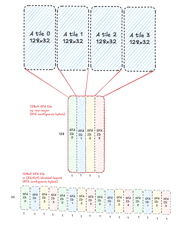
We now understand how to set up an efficient data loading pipeline for our A/B tiles with async TMA loads with 128B swizzling to minimize bank conflicts. We still need to load our scale factors though - which are even weirder, if that is possible! Let’s start by understanding the layout of SFA/SFB in global memory.
Scale factor layouts for tcgen05.mma
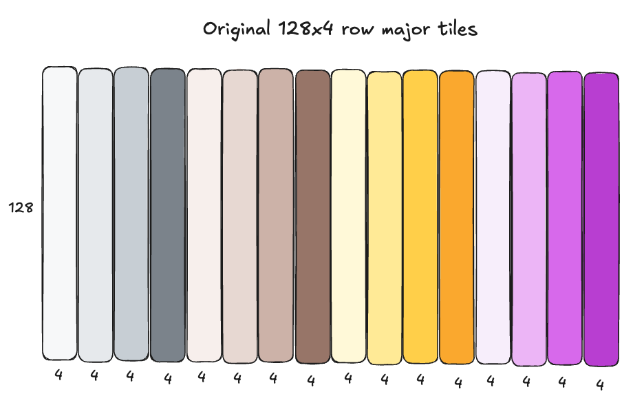
The scale factors SFA and SFB are both float8 e8m0 format, in a special “blocked layout” required for tensorcore consumption with tcgen05.mma, representable as a ((32,4),4) CuTE layout. This is a weird layout at first, so here are some diagrams that help visualize the layout. The top diagram shows the scale factors in simple row major layout as they are originally computed for the input tensor; the bottom layout shows how that row major layout is transformed into blocked layout. These steps happen ahead of time in a torchao quantization kernel which prepares the inputs for a MXFP8 GEMM:
Scales in plain row-major format:
Scales transformed to ((32,4),4) blocked layout
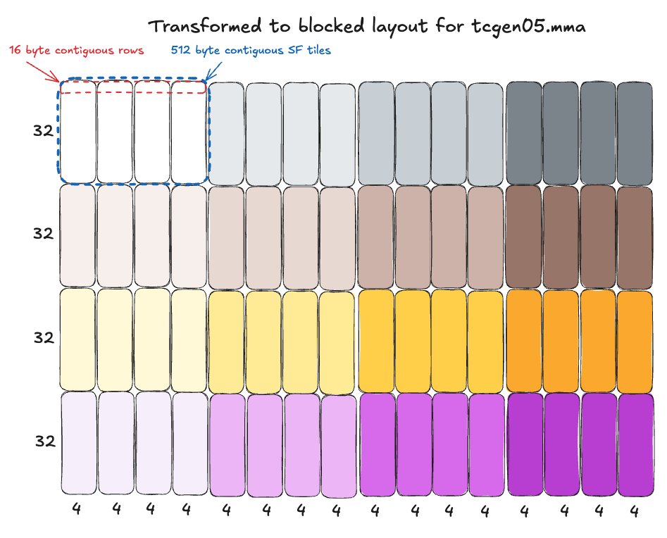
This transformation can be represented as: linear_offset = (row % 32) * 16 + (row // 32) * 4 + col
Breaking this down piece by piece in plain English:
- Add
row * 16bytes to the start offset of every row (e.g. 0, 16, 32, etc), looping back to 0 every 32 rows (i.e.(row % 32) * 16). - Every time we loop back, start adding an additional 4 bytes (i.e.,
... + (row // 32) * 4). - Finally, always just add 1 byte per column (i.e.
... + col) for the final element destination offset, since it is fp8 data.
If you parse that formula and along with the diagram above, you can see how four 32x4 blocks being arranged “horizontally” next to each other, forming 16 byte “superrows” that are contiguous in memory.
It is also important to note that each full ((32,4),4) scale factor tile itself occupies one contiguous 512 byte chunk of memory.
Note we write scales this way because this is the layout required for consumption by tensorcores with the tcgen05.mma.cta_group::2.kind::mxf8f6f4.block_scale.block32 instruction we’ll be using for MMA operations on Blackwell’s 5th gen tensorcores, as we established above.
You can read more details about this layout for SFA in the PTX docs here, or similarly for SFB here.
TMA loads with cross-CTA mbarrier synchronization
We know producer warps on both CTAs will use TMA to load a pipeline of tiles for the consumer on CTA 0 to use for MMAs, but how can we actually implement the cross-CTA coordination in a way that is race-condition free? The key is in the cp.async.bulk.tensor PTX instruction used for TMA loads/stores:
From the PTX docs section on the global to shared variant (with CTA scope):
// global -> shared::cta
cp.async.bulk.tensor.dim.dst.src{.load_mode}.completion_mechanism{.cta_group}{.level::cache_hint}
                                   [dstMem], [tensorMap, tensorCoords], [mbar]{, im2colInfo} {, cache-policy}

.dst =                  { .shared::cta }
.src =                  { .global }
.dim =                  { .1d, .2d, .3d, .4d, .5d }
.completion_mechanism = { .mbarrier::complete_tx::bytes }
.cta_group =            { .cta_group::1, .cta_group::2 }
.load_mode =            { .tile, .tile::gather4, .im2col, .im2col::w, .im2col::w::128 }
.level::cache_hint =    { .L2::cache_hint }
I assume the reader is familiar with TMA, so I won’t go over all of this. The new/important part for our 2 CTA MMA here is: .cta_group::2 modifier - what does it do? From the PTX docs:
.cta_group::2: The mbarrier signal is multicasted either to all the odd numbered CTAs or the even numbered CTAs within the corresponding CTA-Pair. For each destination CTA specified in the ctaMask, the mbarrier signal is sent either to the destination CTA or its peer-CTA based on CTAs %cluster_ctarank parity of shared memory where the mbarrier object mbar resides.
The TL;DR here is this means that we can use .cta_group::2 modifier with a cta_mask of 0b11 (CTA 0 and 1) for mbarrier arrival signals and byte arrival counts from the TMA load to be broadcasted to the corresponding/mapped mbarriers in the CTA pair. This is how we configure TMA loads (cp.async.bulk.tensor) on both CTAs to signal the mbarrier on CTA 0, so upon mbarrier completion the consumer warp there can kick off the 2CTA MMA!
Code
We are ready to look at our (simplified) producer code!
The producer warp master thread will use these tensormaps to issue TMA loads like so:
    // "group" = CTA pair in this context i.e., how many output tiles,
    // covered by a 2CTA cluster, does it take to cover the full output tensor?
    for (int group_id = start_group_id; group_id < total_groups; group_id += num_groups) {
        // ... (removed uninteresting stuff)
        for (int block_k_idx = 0; block_k_idx < num_blocks_k; block_k_idx++) {
            // ... (pointer math) ...

            // ... (smem_empty_mbarrier wait for smem buffer to be ready for re-use)

            // important: CTA 1 maps smem full mbar to CTA 0 via DSMEM!
            uint32_t smem_full_mbar = smem_full_mbar_addr + tma_smem_buf * MBAR_SIZE;
            if (cta_rank == 1) {
                smem_full_mbar = map_smem_addr_to_cta_rank(smem_full_mbar, 0);
            }

            // both CTAs arrive at CTA 0 mbar and set how many bytes to expect!
            mbarrier_arrive_expect_tx(smem_full_mbar, SMEM_A_SIZE + SMEM_B_SIZE + SMEM_SFA_SIZE + SMEM_SFB_SIZE);

            // load A tile. divide K off by 128b swizzle atom size, following tensor map global dims
            int global_k_off = block_k_idx * BK;
            cp_async_bulk_tensor_3d_global_to_shared(
                A_smem,
                a_map_ptr,
                0,                   // start offset along the 128B swizzle dim (i.e., load full thing)
                global_m_off,        // start offset along M
                global_k_off / 128,  // which 128B swizzle span are we in?
                smem_full_mbar
            );

            // load B tile
            cp_async_bulk_tensor_3d_global_to_shared(
                B_smem,
                b_map_ptr,
                0,                  // start offset along the 128B swizzle dim (i.e., load full thing)
                global_n_off,       // start offset along N
                global_k_off / 128, // which 128B swizzle span are we in?
                smem_full_mbar
            );

            // load SFA
            const uint32_t k_off_sf = (uint32_t)(global_k_off / 32 / 4);
            cp_async_bulk_tensor_4d_global_to_shared(
                SFA_smem,
                sfa_map_ptr,
                0,                       // start idx along 16 byte "superrow" dim (i.e., load full thing)
                0,                       // start idx along 32x16 subtile dim (i.e., load full 32x16 subtile)
                global_k_off / 32 / 4,   // which 128x4 tile are we along the K dimension?
                global_m_off/128,        // which 128x4 tile are we along the M dimension?
                smem_full_mbar
            );

            // load SFB
            cp_async_bulk_tensor_4d_global_to_shared(
                SFB_smem,
                sfb_map_ptr,
                0,                       // start along 16 byte "superrow" dim (i.e., load full thing)
                0,                       // start along 32x16 subtile dim (i.e., load full 32x16 subtile)
                global_k_off / 32 / 4,   // which 128x4 tile are we along the K dimension?
                global_n_off_sfb / 128,  // which 128x4 tile are we along the N dimension?
                smem_full_mbar
            );

            // move to next smem buffer in the circular queue
            tma_smem_buf = (tma_smem_buf + 1) % QUEUE_SIZE;
        }
    }
Consumer
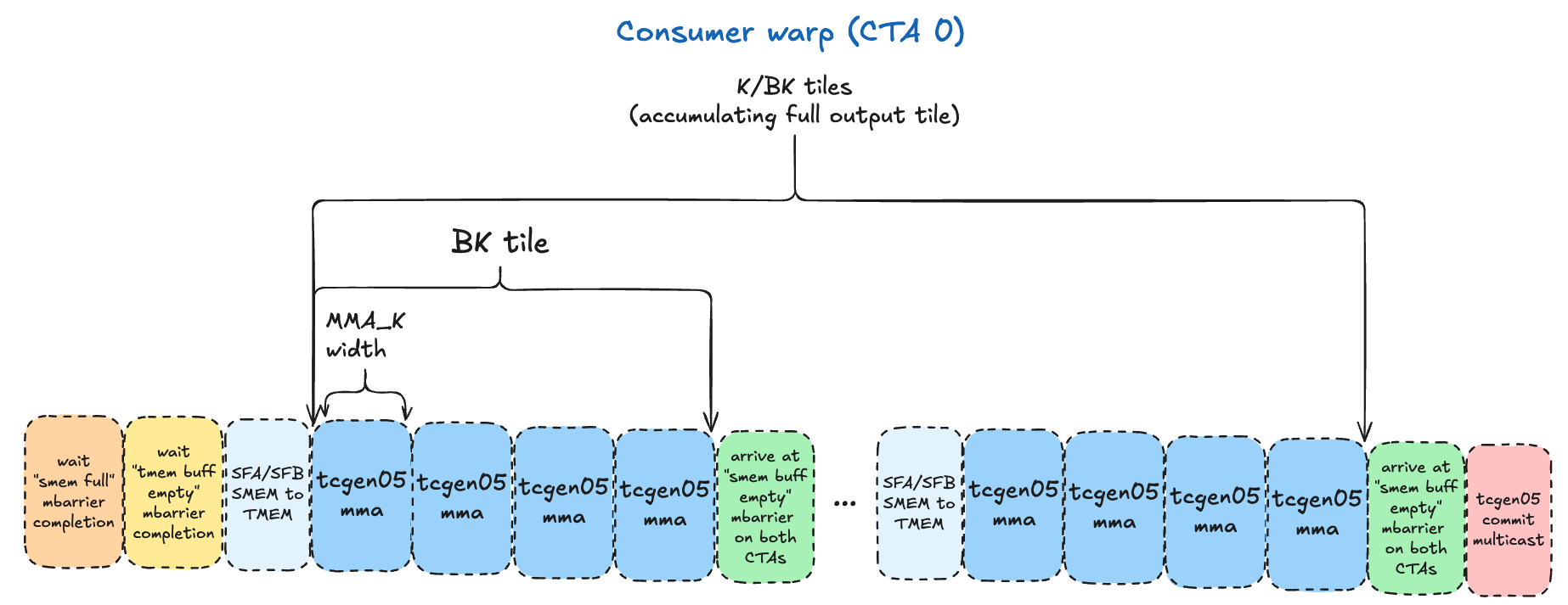
We have one consumer warp that runs only on CTA 0, since only one CTA issues the 2CTA tcgen05.mma instruction. It is responsible for iterating through the A/B tiles, in increments dictated by the tcgen05.mma dimensions selected. We’ll start with: MMA_M=128, MMA_N=128, MMA_K=32.
The logical flow is as follows:
- The valid options for block scaled
tcgen05.mmawithcta_group::2are in the PTX docs here. - For
K/BKiterations (we tile over the K dimension in increments ofBK), the consumer does the following:- For each
BK=128tile, we’ll have 4MMA_K=32iterations, issuingtcgen05.mmainstructions, accumulating the outputs in a given TMEM buffer.- Before each
tcgen05.mma, we need to copy the SFA/SFB tiles from SMEM to TMEM - as we established above, this is required for the MMA instruction. - After the 4 MMAs have been issued, the consumer commits the MMAs and arrives at the
smem_empty_mbarmbarrier for that buffer via a tcgen05.commit multicast to BOTH CTAs. This serves the dual purposes of registering the mbarrier to track the completion of the MMAs, and signaling to the producers on both CTAs that particular SMEM buffer is ready to be re-used. Note the instruction ordering guarantees are important here, to avoid race conditions where the producer starts overwriting the SMEM buffer with new data before thetcgen05.mmais done reading it.
- Before each
- For each
- After completing the tiling loop over the
Kdimension, we arrive at themma_mbarwith another tcgen05.commit multicast, which makes the mbarrier object given to it track the completion of all prior asynctcgen05.mmainstructions issued by the same thread. We use amma_mbarmbarrier for the specific TMEM buffer being used here, and when the epilogue warpgroup waits on this mbarrier with acquire/release semantics, it is guaranteed the commited batch of MMAs have completed - and we have the final accumulated result for this128x128output tile in TMEM, ready for the epilogue to use!
Before we begin, we need to understand the shared memory descriptors and instruction descriptors for the tcgen05.mma instruction.
Shared memory descriptor
A shared memory descriptor is a 64 bit value that encodes various attributes of a MMA operand in SMEM. In practice, this involves a tedious process of carefully using bitwise operations to encode:
- Matrix start address
- Leading dimension byte offset (LBO)
- Stride dimension byte offset (SBO)
- Swizzling mode
Of these, the only new concepts we must grapple with are LBO and SBO. I found the PTX docs explanations of these concepts unhelpful, and instead used a combination of gaunerst’s blog tcgen05 for dummies and the Modular blog on BF16 GEMMs for Blackwell, both of which I’d suggest reading.
- LBO technically encodes the stride between two 8x1 columns of
8x16Bcore matrices, within a 8x2 tile of core matrices. That is a mouthful, and in our data loading layout, it is much simpler to just think about it as the stride between 2 columns/strips of8x16Bmatrices. You can see an example of this in my Hopper GEMM kernel using WGMMA, which has smem descriptors with the same LBO/SBO concepts, where I set the LBO asBM*16. However, luckily for us, for a K-major matrix where swizzling is used, the LBO is ignored/not used, so we don’t have to worry about it. - SBO encodes the stride between one core matrix and the next in physical memory.
To figure out how exactly to encode the SBO, we can refer to the canonical CuTe layout for a K-major matrix with 128B swizzling from the PTX docs (which will be a feat unto itself):
((8,m),(T,2k)):((8T,SBO),(1,T))
Breaking this down:
- Shape:
((8,m),(T,2k)) - Stride:
((8T,SBO),(1,T)) - Where:
T= 128 / bits per element (128 / 8 bits per float8 e8m0 = 16B)m= number of core matrices along the M dimension2k= number of core matrices across the K dimension
This means:
- Hierarchical shape of
(m,2k)grid of(8,16B)core matrices 8Tstride between rows of each8x16Bcore matrixSBOstride between themcore matrices along the M dimension1stride along T (the 16B row of each8x16Bcore matrix)Tstride between the2kcore matrices along the K dimension
So the TL;DR is the SBO is the stride between core matrices along the M dimension. Remember in our case, the producer loads SMEM as BMx128B contiguous chunks. So the stride between 2 core matrices will be 8x128B=1024B.
We can encode a shared memory descriptor for A and B tiles like this:
// see: https://docs.nvidia.com/cuda/parallel-thread-execution/#tcgen05-shared-memory-descriptor
__device__ uint64_t matrix_desc_encode(uint64_t x) {
    // grabs 18 rightmost bits and shifts right by 4 to get bits 3-17 (14 bits)
    return (x & 0x3FFFF) >> 4;
}

// see: https://docs.nvidia.com/cuda/parallel-thread-execution/#tcgen05-shared-memory-descriptor
__device__ uint64_t make_smem_desc(uint32_t smem_shared_addr) {

    // bits 0-13: matrix_desc_encode(matrix addr)
    uint64_t desc = matrix_desc_encode(smem_shared_addr);

    // bits 16-29: matrix_desc_encode(leading dim byte offset)
    // implied to be 1 for swizzled layouts, see: https://docs.nvidia.com/cuda/parallel-thread-execution/#tcgen05-leading-dimension-byte-offset

    // bits 32-45: matrix_desc_encode(stride dim byte offset)
    // SBO (stride byte offset) is stride between swizzle atoms which are (8x128 matrix of e4m3 in this 128b swizzle setup)
    uint64_t SBO = 8 * 128;
    desc |= (matrix_desc_encode(SBO) << 32);

    // bits 46-49: fixed value of 0b001
    desc |= (1ULL << 46ULL);

    // bits 61-63: swizzle mode (2 = 128b swizzle)
    desc |= (2ULL << 61ULL);
    return desc;
}
Shared memory descriptors for SFA/SFB
Similarly, the tcgen05.mma instruction requires smem descriptors for SFA/SFB. This is the area I admit I do not feel 100% confident in my understanding, but was still able to get it to work. This is largely because it is completely undocumented in the PTX docs as far as I can tell, so I was forced to rely on a combination of experimentation and the advice of gaunerst from the GPU Mode discord, who had wrangled with similar problems for NVFP4 GEMMs.
The SFA/SFB are not swizzled, at least not in the traditional sense. They are in the blocked layout required for tensorcores, described above. Thus, one would think we could divide the 512 SFA/SFB (laid out as ((32,4),4)) into 4x1 grid of 8x16B core matrices and set the LBO accordingly, using the “no swizzle” mode calculation above. However, empirically, this seems to result in inaccurate results. What DOES work, is simply not setting the LBO at all! gaunerst mentioned for NVFP4 he discovered this through trial and error, due to lack of documentation, and I assumed the same could be true for MXFP8 - and indeed it is.
So my understanding now is that the blocked layout is treated as a form of swizzling, and as mentioned previously the PTX docs DO state for swizzled SMEM layouts we ignore the LBO, so that is why we ignore it here.
For the SBO, remember the layout is ((32,4),4) which has 16B contiguous “super-rows.” So to get from one group of 8 rows to the next, the stride is simply 8x16B:
__device__ uint64_t make_sf_smem_desc(uint32_t smem_shared_addr) {
    // bits 0-13: matrix_desc_encode(matrix addr)
    uint64_t desc = matrix_desc_encode(smem_shared_addr);

    // bits 16-29: matrix_desc_encode(leading dim byte offset)
    // not used for sfa/sfb, blocked layout treated as form of swizzling?

    // bits 32-45: matrix_desc_encode(stride dim byte offset)
    // SBO: stride between groups of 8 rows
    uint64_t SBO = 8*16;
    desc |= (matrix_desc_encode(SBO) << 32);

    // bits 46-49: fixed value of 0b001
    desc |= (1ULL << 46ULL);

    // bits 61-63: swizzle mode (0 = no swizzle)
    return desc;
}
Instruction descriptor
tcgen05.mma also requires an instruction descriptor which is a 32 bit value that encodes various information about the MMA itself, such as:
- A/B tile dtypes
- SFA/SFB dtypes
- If A/B tiles are transposed or non-transposed (i.e., MN-major or K-major)
- M dimension of A tile (
MMA_M) - N dimension of B tile (
MMA_N) - Scale factor A ID
- Scale factor B ID
The only non-obvious concepts here are the SFA/SFB “IDs” - what are these? Taking a look at the linked PTX docs, they basically hold a value from 0-3 (inclusive) which defines which columns of the SFA/SFB in TMEM to use for the given tcgen05.mma.
We will revisit these concepts after we see how the SFA/SFB are laid out in TMEM after we copy them there from SMEM using tcgen05.cp!
tcgen05.cp
To transfer the SFA/SFB tile from SMEM to TMEM, there are a couple of options:
- Load SMEM -> registers via ld.shared then registers -> TMEM via tcgen05.st. Or:
- Use tcgen05.cp to asynchronously copy data directly from SMEM to TMEM.
The latter skips an extra copy which is obviously preferable, let’s see how it works:
tcgen05.cp.cta_group.shape{.multicast}{.dst_fmt.src_fmt} [taddr], s-desc;

.cta_group = { .cta_group::1, .cta_group::2 }
.src_fmt   = { .b6x16_p32 , .b4x16_p64 }
.dst_fmt   = { .b8x16 }
.shape     = { .128x256b, .4x256b, .128x128b, .64x128b**, .32x128b*** }
.multicast = { .warpx2::02_13** , .warpx2::01_23**, .warpx4*** }
Breaking it down:
[taddr]argument: tensor memory destination addresss-desc: (another) shared memory descriptor (everyone’s favorite!) for the source SMEM buffer.cta_group: specifies the number of CTAs whose Tensor Memory is accessed when a single thread of a single CTA executes thetcgen05.cpinstruction. Remember, the consumer is running on CTA 0 only, but we need SFA/SFB from both CTAs SMEM buffers to be copied into TMEM! NVIDIA provides acta_group::2variant that does this - when the consumer warp issues this instruction on CTA 0, both CTAs will copy identical regions of SMEM to TMEM, on their respective SMEM/TMEM buffers..src_fmt/.dst_fmt: optionally decompress from SMEMsrc_fmtto TMEMdst_fmt(not used in our kernel, I haven’t actually seen these used in practice, I am curious about the use case).shape: the shape of the data being copied (rows x bytes).multicast: multicast to certain warp zones.
The PTX docs on .multicast are a bit poorly phrased in my opinion:
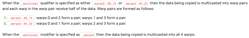
The TL;DR is when it says “pairs of warps” or “broadcast to all 4 warps,” what I believe it means are warp zones of TMEM, i.e., when you use .32x128b, a 32 row by 128 bit (careful with that lowercase vs uppercase B!) chunk of SMEM will be copied to TMEM, into all 4 of the 32 row zones that have warp restricted access, as described previously.
As an aside: Why multicast to TMEM though? The scales are only used by the
tcgen05.mmainstruction, running on tensorcores, we don’t have a warpgroup accessing them in TMEM at all.
The exact mechanism isn’t documented, but empirically
.warp4xis required for.32x128bcopies from SMEM to TMEM. One possible reason is that we have 4 tensorcores per SM (B200), and 4 access restricted zones of TMEM - maybe there are “tensorcore access restrictions” very similar to the “warp access restrictions” we know exist?
Or maybe it is purely so 4 tensorcores can do matmul operations that have overlapping requests for scale factors, without serializing the requests? One scale factor covers
1x32chunk of input data, so for 28x16Bcore matrices would use the same8x1set of scale factors.
To decide on a shape, we need to look at our tcgen05.mma instruction M/N/K dimensions, calculate how many scale factor tiles (or what portions of one) we need for that MMA:
MMA_M/MMA_N/MMA_K=128/128/32means A tile will be128x32and B tile128x32SFAshape for this MMA:128x32divided by scaling factor (32) =128x1(one slice of a128x4scale factor tile).SFBshape will be the same in the case, even though it is replicated so both CTAs have the full N dimension, the full MMA_N is still 128 here.
So technically for a single tcgen05.mma we only need access to a 128x1 slice of the 128x4 512 byte SFA/SFB tiles. It will take 4 tcgen05.mma to consume a full 128x4 scale factor tile. Should we load the full SFA/SFB tiles all at once, then do 4x MMAs with them - or try to pipeline individual pairs of tcgen05.cp -> tcgen05.mma operations?
Looking into it, I think only the former is possible: in the blocked layout in shared memory, the 4 “32 element column” strips that compose this 128x1 slice are not in contiguous memory (see blocked layout diagram here) - it would be inefficient to try to do 4 separate loads PER 128x1 slice, PER scale factor tile (4x4 = 16 total loads). It will be far more efficient to just load the whole SFA/SFB in one contiguous 512B chunk. Furthermore, none of the .shape operations seems to be granular enough to copy the SFA/SFB data just for a single MMA - and it just so happens that a .32x128b shape chunk is exactly 32*128b/8bits per byte= 512B, our exact scale factor size! Note that the 128b / 16byte width of this scale factor will consume only 4 columns of TMEM - as each TMEM cell/column is 4 bytes wide.
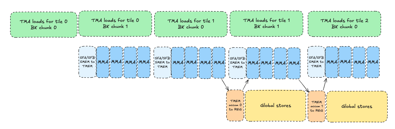
This leads us to our final instruction: tcgen05.cp.cta_group::2.32x128b.warpx4. We will issue it, then issue 4x tcgen05.mma operations to consume it all, then finally arrive at our smem_empty_mbar mbarrier for this particular SMEM buffer of the queue, to signal the producer it is safe to re-use. At this point, we have successfully processed one BMxBK of A and BKxBN of B - yay!
We will move onto the next SMEM buffer in the queue, processing BK-width tiles until we have accumulated along the full K dimension of our inputs, producing our final result for this output tile in TMEM.
Async tcgen05.cp + tcgen05.mma instruction ordering?
If we are issuing all these async tcgen05.cp and tcgen05.mma instructions, how can we be sure they are executed in the correct order?
Luckily, NVIDIA has designed these instructions to be pipelined in the manner we are doing now. As a general rule, async tcgen05 instructions may not be executed by the async proxy in the order they were issued; however, there exist certain ordering guarantees for pairs of instructions issued on the same thread (in this case, our consumer master thread), including tcgen05.cp.cta_group::N + tcgen05.mma.cta_group::N (with same N):
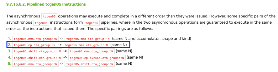
Note: these order guarantees are also important for calculating TMEM storage requirements. Thanks to these ordering guarantees, the SFA/SFB sections of TMEM can be re-used for each BK tile we process; when the next MMA loop for the next BK tile starts, the previous batch of MMAs using the prior SFA/SFB are guaranteed to be done!
Thank you NVIDIA, for implicitly handling what would otherwise be a gnarly race condition :)
SFA/SFB IDs
Now that we understand the layout of SFA/SFB in TMEM, let’s revisit the concept of “SFA/SFB ID” that we need to encode in our tcgen05.mma instruction descriptor. First, let’s consult the PTX docs.
Here is a diagram from the PTX docs illustrating the SFA layout in TMEM and the columns selected for each SFA ID, for our .block32 and MMA_K=32:
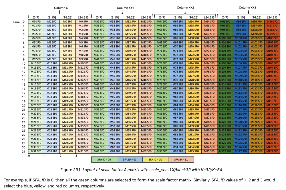
As you can see, when sfa_id is 0, the 4 32x1 green columns are selected; when it is 1, the 4 blue columns are selected, and so on. Why do we select these particular 4 columns? Well, if we remember our blocked layout transformation described above, these 4 32x1 columns correspond to a 128x1 strip of the original row-major SFA. That 128x1 strip of SFA provides scaling factors for a 128x32 chunk of the A tile - which just so happens to be our exact MMA_MxMMA_K size! So for each MMA we do as we iterate, we select SFA_ID=0 for the first one, the SFA_ID=1 for the next MMA, etc finishing with SFA_ID=3 for the final MMA in that BK chunk.
Here is a diagram that helps visualize how SFA ID 0/1/2/3 relates to the original 128x128 A tile it was derived from:
The SFB ID works the same way, except there are up to 8 columns selected, since MMA_N can go up to 256, while MMA_M can only go up to 128.
tcgen05.commit
Our final step is to commit the batch of MMAs and register a mbarrier object on both CTAs to track their completion. This will allow the epilogue warpgroup on each CTA to wait on this mbarrier completion, and perform the processing and storage to global memory once ready! We can do this with the tcgen05.commit instruction, which, thank goodness, is simpler to parse:
tcgen05.commit.cta_group.completion_mechanism{.shared::cluster}{.multicast}.b64
                                                            [mbar] {, ctaMask};

.completion_mechanism = { .mbarrier::arrive::one }
.cta_group            = { .cta_group::1, .cta_group::2 }
.multicast            = { .multicast::cluster }
Breaking it down:
[mbar]= pointer to mbarrier objectctaMask= optional arg to specify which CTAs to multicast to (see.multicastbelow).completion_mechanism= must be.mbarrier::arrive::onewhich indicates an mbarrier with expected arrival count of 1 will be used as the completion mechanismcta_group= similar to prior instructions, we have a.cta_group::2variant which will track completion of all prior asynchronoustcgen05instructions that were also issued by this thread with thecta_group::2modifier (tcgen05.cp,tcgen05.mma)..multicast= we can optionally specify.multicast::clusterto multicast the mbarrier arrival signal to the CTAs specified incta_mask..shared::cluster= optional scope to use a cluster-scoped address (DSMEM) for the mbarrier
Parsing this, we construct our final instruction for committing a batch of async tcgen05 instructions issued with .cta_group::2, using a CTA mask that will broadcast the arrival signal to the same mbarrier location in SMEM on both CTAs, via DSMEM:
// see: https://docs.nvidia.com/cuda/parallel-thread-execution/#tcgen05-mma-instructions-mma
__device__ __forceinline__ void tcgen05_commit_multicast(uint32_t mbar_addr, uint16_t cta_mask) {
    asm volatile(
        // tcgen05.commit.cta_group.completion_mechanism{.shared::cluster}{.multicast}.b64
        // see: https://docs.nvidia.com/cuda/parallel-thread-execution/#tcgen-async-sync-operations-commit
        "tcgen05.commit.cta_group::2.mbarrier::arrive::one.shared::cluster.multicast::cluster.b64 [%0], %1;"
        :
        : "r"(mbar_addr), "h"(cta_mask)
        : "memory"
    );
}
Double buffering TMEM
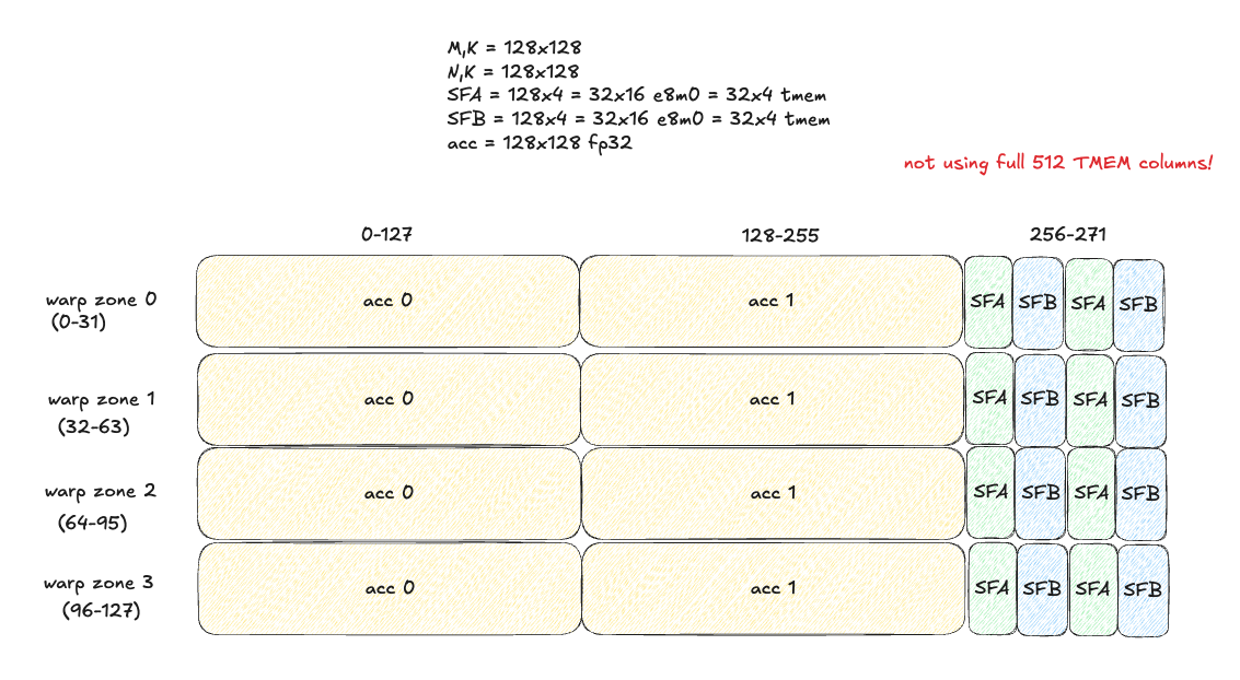
It is important to remember that we want to make full use of TMEM if possible, and also minimize tensorcore idle time - as discussed previously, one way to help achieve this goal is double-buffering TMEM, so we always can have 2 MMAs in flight (if the accumulator dimensions can fit along with SFA/SFB!).
Our initial TMEM layout looks like this (note we are not fully utilizing our valuable TMEM resources - a high bandwidth, low latency resource that lives physically close to the tensorcores!)
Code
The core processing loop in the consumer looks as follows at this point:
   // persistent kernel loop, static schedule (group = 2 CTA group covering 256x128 output tile)
   for (int group_id = start_group_id; group_id < total_groups; group_id += num_groups) {

        // calculate base offsets for TMEM accumulator, SFA/SFB TMEM start column
        int buffer_offset = mma_tmem_buf * TMEM_WIDTH;
        int tmem_accum_addr = tmem_base_addr + buffer_offset;
        int tmem_sfa_base_addr = tmem_base_addr + buffer_offset + BN;
        int tmem_sfb_base_addr = tmem_base_addr + buffer_offset + BN + SFA_TMEM_COLS;

        // wait for epilogue mbarrier to signal this TMEM buffer can be safely re-used
        if (blocks_processed >= TMEM_BUFFERS) {
            mbarrier_wait_parity(epilogue_mbar_addrs[mma_tmem_buf], epilogue_parity[mma_tmem_buf]);
            epilogue_parity[mma_tmem_buf] ^= 1;
        }

        // iterate through BK width tiles along K
        for (int block_k_idx = 0; block_k_idx < num_blocks_k; block_k_idx++) {
            mbarrier_wait_parity(smem_full_mbar_addrs[mma_smem_buf], smem_full_parity[mma_smem_buf]);
            smem_full_parity[mma_smem_buf] ^= 1;

            constexpr int BUFF_SIZE = SMEM_A_SIZE + SMEM_B_SIZE + SMEM_SFA_SIZE + SMEM_SFB_SIZE;
            const int smem_sfa_base = mma_smem_buf * BUFF_SIZE + SMEM_A_SIZE + SMEM_B_SIZE;
            const int smem_sfb_base = smem_sfa_base + SMEM_SFA_SIZE;
            constexpr int SWIZZLE_WIDTH_K = 128;

            // at this point, in the smem buffer for this stage, we have:
            // - A tile [BM,BK] = [128,128]
            // - B tile [BN,BK] = [128,128]
            // - SFA [BM/128, BK/32/4, 32, 16] = [1, 1, 32, 16] = one 512 byte sf
            // - SFB [BN/128, BK/32/4, 32, 16] = [1, 1, 32, 16] = one 512 byte sf

            // A/B tiles in smem and SFA/SFB in tmem will take 4 mmas to use.
            // each mma uses:
            // 128x32 of A
            // 128x32 of B
            // 128x1 of SFA laid out as (32,4) in tmem
            // 128x1 of SFB laid out as (32,4) in tmem
            for (int bk_chunk = 0; bk_chunk < BK / SWIZZLE_WIDTH_K; bk_chunk++) {
                uint64_t sfa_desc = make_sf_smem_desc<SF_BK>(smem + smem_sfa_base + 512 * bk_chunk);
                uint64_t sfb_desc = make_sf_smem_desc<SF_BK>(smem + smem_sfb_base + 512 * bk_chunk);

                // each sf tile is 16 bytes / 4 tmem cells wide. we have one sf tile per BK chunk.
                // this does 32x16byte smem->tmem load broadcasted to all 128 rows of tmem (all 4 warp zones)
                tcgen05_cp_smem_to_tmem(sfa_desc, tmem_sfa_base_addr, 0, 4 * bk_chunk);
                tcgen05_cp_smem_to_tmem(sfb_desc, tmem_sfb_base_addr, 0, 4 * bk_chunk);

                for (int mma_iter = 0; mma_iter < SWIZZLE_WIDTH_K / MMA_K; mma_iter++) {
                    const int a_chunk_off = bk_chunk * BM * SWIZZLE_WIDTH_K;
                    const int b_chunk_off = bk_chunk * (BN / CTA_GROUP_SIZE) * SWIZZLE_WIDTH_K;
                    const int a_k_off = a_chunk_off + mma_iter * MMA_K;
                    const int b_k_off = b_chunk_off + mma_iter * MMA_K;

                    uint32_t smem_buff_a = smem + mma_smem_buf * BUFF_SIZE;
                    uint32_t smem_buff_b = smem_buff_a + SMEM_A_SIZE;

                    // A/B smem descs
                    uint64_t smem_a_desc = make_smem_desc(smem_buff_a + a_k_off);
                    uint64_t smem_b_desc = make_smem_desc(smem_buff_b + b_k_off);

                    // encode tcgen05.mma instruction descriptor.
                    // SFA_ID is odd. for .block_32 mma scaling, it basically selects 4 separate 32x1 strips, separated by 4 cols each
                    // so what *was* as 128x1 sf column before the transform to ((32,4),4) blocked layout.
                    // therefore, this 128x1 sf column corresponds exactly to a 128x32 chunk of A tile,
                    // which matches our MMA_M=128, MMA_K=32.
                    uint32_t idesc = 0;
                    tcgen05_encode_idesc<CTA_GROUP_SIZE * MMA_M, MMA_N>(idesc, mma_iter, mma_iter);

                    // only disable accumo on the first mma of each block
                    int enable_accum = (block_k_idx == 0 && bk_chunk == 0 && mma_iter == 0) ? 0 : 1;

                    // i *think* that the `tmem_base_addr` of SFA and SFB should stay constant
                    // while we are using the same 512b scale factor tile for four MMAs,
                    // which use one 128x1 (or four 32x1) sf cols.
                    // we use same tmem base address and increment `sfa_id` to communicate
                    // which sf cols to select for that MMA.
                    int tmem_sfa_tile_addr = tmem_sfa_base_addr + 4 * bk_chunk; // 32x16 for each bk chunk, i.e. 4 cols of tmem
                    int tmem_sfb_tile_addr = tmem_sfb_base_addr + 4 * bk_chunk;
                    tcgen05_mma_mxfp8(smem_a_desc, smem_b_desc, tmem_sfa_tile_addr, tmem_sfb_tile_addr, tmem_accum_addr, idesc, enable_accum);
                }
            }

            // cta 0 signals to both ctas the smem buffer can now be safely re-used
            tcgen05_commit_multicast(smem_empty_mbar_addrs[mma_smem_buf], cta_mask);
            mma_smem_buf = (mma_smem_buf + 1) % QUEUE_SIZE;
        }

        // cta0 signals to both ctas the tmem accum buff is ready for epilogue
        tcgen05_commit_multicast(mma_mbar_addrs[mma_tmem_buf], cta_mask);
        mma_tmem_buf = (mma_tmem_buf + 1) % TMEM_BUFFERS;
Epilogue
We have one epilogue warpgroup (4 warps) that is responsible for reading output tiles from TMEM and storing the result in global memory. We use a full warpgroup due to the following constraints:
TMEM is not like SMEM or GMEM in the sense that it has rigid warp-level access restrictions. Each warp in the warpgroup is restricted to accessing only 32 specific rows of TMEM:
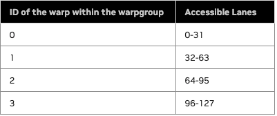
Furthermore, within a warp-zone of TMEM, we cannot read arbitrary elements, but rather groups of columns, using the tcgen05.ld instruction to load 16 or 32 rows of N columns each into a register fragment on each thread in the warp.
Therefore, our high level logic for the epilogue warpgroup is as follows:
- Load from TMEM to registers
- Arrive at
epilogue_mbarmbarrier to signal to consumer warp on CTA 0 that the TMEM buffer can be safely re-used - Issue global store instructions to write final result to global memory
- Move on to next TMEM buffer
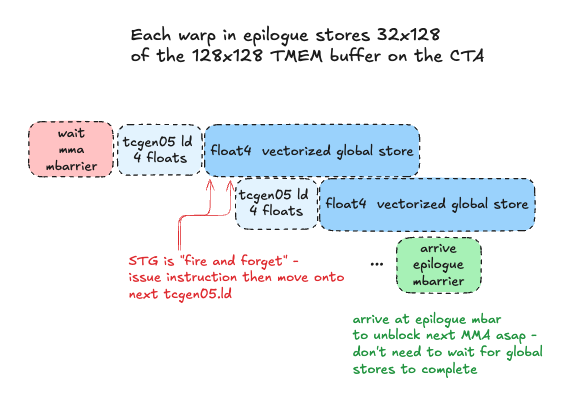
tcgen05.ld, tcgen05.wait
To read out the full 128x128 output tile a given CTA has accumulated in TMEM, we will have each warp issue a tcgen05.ld async load from TMEM to registers.
We construct our final instruction: tcgen05.ld.sync.aligned.32x32b.x4.b32, which will load 32 rows of 4 columns each, where each column is 32 bits wide (4 bytes, one full TMEM cell). This 32x16 byte chunk corresponds exactly to a float4 16 byte global store per thread in each warp, so we can pipeline TMEM loads with global stores.
Once the accumulator data is in registers, we are now free to arrive at the epilogue_mbar mbarrier, which the consumer warp is waiting on, to signal it is safe to re-use the TMEM buffer for computing the next output tile. It is crucial we send this signal ASAP, to unblock the next batch of MMAs and keep tensorcores busy. We DO NOT wait for the final store to global memory to complete, as this is a high latency operation that we would like to overlap with useful tensorcore work as much as possible. We read TMEM to registers, arrive at the mbar to unblock next MMAs, then issue float4 vectorized stores PTX instruction to use STG.128 SASS instruction that stores 16 bytes per thread to global memory in coalesced, vectorized global stores.
Enforcing instruction ordering and preventing race conditions
Note the tcgen05.ld is asynchronous - how do we ensure that when we issue the global stores, the data is actually ready in registers? For this we can use tcgen05.wait::ld, which waits on all prior async tcgen05.ld instructions issued by the executing thread have completed. This instruction has no arguments or options really, we can use it like this, we put it directly after our tcgen05.ld instruction in our wrapper function for it, since there is a hard dependency on this for the next step (global store from registers):
    // from PTX docs: "Prevents subsequent tcgen05.mma from racing ahead of the tcgen05.ld"
    asm volatile("tcgen05.wait::ld.sync.aligned;");
Code
Our core epilogue loop looks like this (simplified for brevity):
    for (int group_id = start_group_id; group_id < total_groups; group_id += num_groups) {
        // ...(compute block id this CTA is responsible in this 2CTA MMA output tile)...
        // ...

        // wait for consumer to signal this output tile in TMEM is ready for processing
        mbarrier_wait_parity(mma_mbar_addrs[epilogue_tmem_buf], mma_parity[epilogue_tmem_buf]);
        mma_parity[epilogue_tmem_buf] ^= 1;

        // fence that ensures all previously committed
        // tcgen05.mma operations are complete with results visible in tmem to this thread
        asm volatile("tcgen05.fence::after_thread_sync;");

        int tmem_addr_reg = tmem_base_addr + epilogue_tmem_buf * TMEM_WIDTH;

        #pragma unroll
        for (int i = 0; i < BN/COLS_PER_THREAD; i++) {
            float c_reg[COLS_PER_THREAD];
            const int tmem_base_row = ep_warp_id * 32;
            const int tmem_base_col = i * COLS_PER_THREAD;
            tcgen05_ld_tmem_to_reg(tmem_addr_reg, tmem_base_row, tmem_base_col, c_reg);

            const int c_row = block_m * BM + ep_warp_id * 32 + lane_id;
            const int c_col = block_n * BN + i * COLS_PER_THREAD;

            *reinterpret_cast<float4*>(C + c_row * N + c_col) = *reinterpret_cast<float4*>(&c_reg);
        }

        mbarrier_arrive(epilogue_mbar_addrs[epilogue_tmem_buf]);
        epilogue_tmem_buf = (epilogue_tmem_buf + 1) % TMEM_BUFFERS;
    }
We’ll see how we can optimize the epilogue further later :)
Benchmarks and conclusion
| Matrix Size | Custom Kernel | torch._scaled_mm | Speedup |
|---|---|---|---|
| M=2048, K=2048, N=2048 | 478.49 TFLOPS | 996.05 TFLOPS | 0.48x |
| M=4096, K=4096, N=4096 | 877.78 TFLOPS | 2538.40 TFLOPS | 0.35x |
| M=8192, K=8192, N=8192 | 1171.53 TFLOPS | 2691.93 TFLOPS | 0.44x |
| M=16384, K=16384, N=16384 | 1235.61 TFLOPS | 2571.48 TFLOPS | 0.48x |
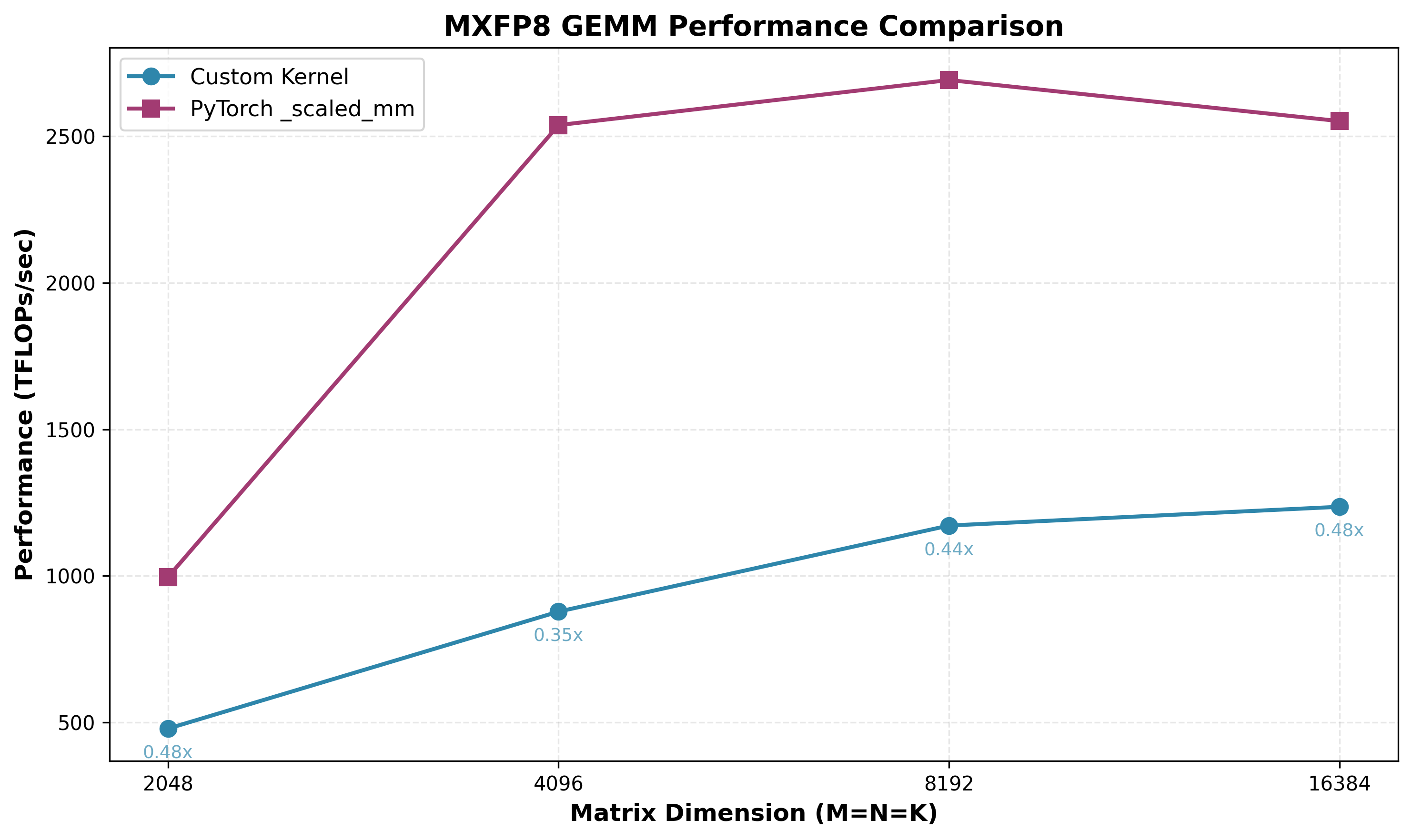
Wow, that was a lot to understand, let alone implement correctly - yet here we are, standing brow-beaten at only 35%-48% of cuBLAS performance! This is not an ultra-naive kernel, we used reasonable design patterns typical in high performance GEMM implementations… What are the gaps? What can we do to improve this?
Optimization 1: Increasing MMA_N to 256, overlapping 128 columns of TMEM accumulator buffers and ping-pong between them
As hinted at previously, we would like to use the maximum MMA_N dimension supported by tcgen05.mma with .cta_group::2, to maximize arithmetic intensity, along with double+ buffering of TMEM, to overall maximize our tensorcore utilization. The problem is we don’t have enough TMEM to store 2 accumulators and SFA/SFB!
To fit everything in TMEM, one thing we can do is overlap some columns of our 2 accumulators, ping-ponging between them, and using more granular mbarriers to track which overlapped vs non-overlapped sections of each accumulator separately. In the epilogue, we will always read the overlapped section of TMEM first into registers, so we can immediately arrive at the epilogue_mbar mbarrier for that region of TMEM and unblock the next MMA asap.
This adds additional synchronization overhead, but we should get a net benefit from the increased arithmetic intensity and tensorcore utilization.
Difference 1: SFB tiles
Our SFB tile now has 256 N dimension instead of 128, so we now need 2 full 128x4 SFB tiles to cover the full MMA_N=256 dimension:
- A tile [BM,BK] = [128,128]
- B tile [BN,BK] = [256,128]
- SFA [BM/128, BK/32/4, 32, 16] = [1, 1, 32, 16] = one 512 byte sf
- SFB [BN/128, BK/32/4, 32, 16] = [2, 1, 32, 16] = two 512 byte sfs
Difference 2: TMEM layout
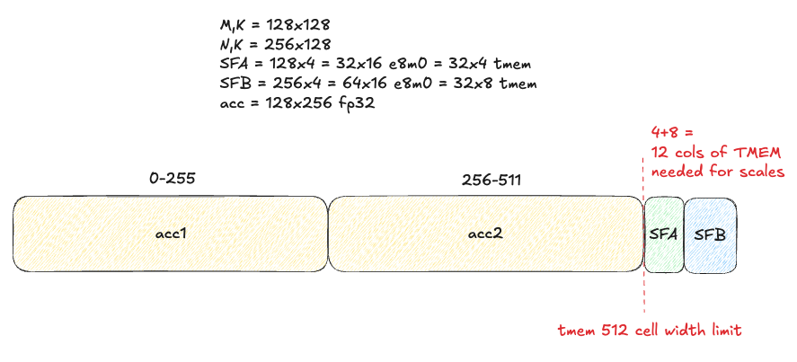
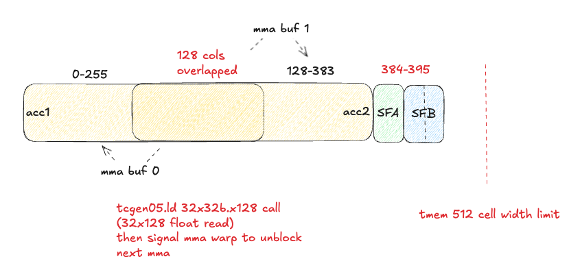
We can now calculate: how many overlapped TMEM columns do we need?
- 256 * 2 (accumulators) + 4 (one SFA tile) + 4 * 2 (two SFB tiles) = 524 columns. That is 12 more columns than the 512 limit.
Ideally we could only overlap those 12 columns, but we need to also co-design this with the tcgen05.ld shape constraints - there is no way to read 12 columns in one tcgen05.ld instruction, although we could do 3x of the 4 column reads. Another thing to remember here is the pointer math may get complicated if we start mixing different tcgen05.ld - and developing this was already extremely challenging with the simpler, non-overlapping strategy! Let’s start with a simple overlapping strategy, where we overlap 128 TMEM columns, which results in the two accumulators covering 384 columns, evenly divisible into 3x 128 column chunks like so:
Difference 3: Epilogue mbarriers
Instead of 2 epilogue_mbar mbarriers, one for each MMA accumulator buffer in TMEM, we’ll have 3 mbarriers for this:
- One for TMEM columns 0-127 (non-overlapped region of MMA buffer 0)
- One for TMEM columns 128-255 (overlapped columns)
- One for TMEM columns 256-383 (non-overlapped region of MMA buffer 1)
We have to be careful with our mbarrier arrivals tracking here, as there are different cases when it’s our first pass through the queue versus when we start re-using buffers. This tedious bookkeeping is difficult, but not that interesting, so I will not spend time on it here - interested readers can check out the code!
Benchmarks
After some struggle, I managed to get MMA_N=256 with 128 TMEM columns of overlap between accumulators working, and our TFLOPs/sec increase drastically - the struggle was worth it!
| Matrix Size (M×K×N) | Custom Kernel | torch._scaled_mm | Speedup |
|---|---|---|---|
| 2048×2048×2048 | 797.73 TFLOPS | 996.05 TFLOPS | 0.80x |
| 4096×4096×4096 | 1443.69 TFLOPS | 2538.40 TFLOPS | 0.57x |
| 8192×8192×8192 | 1900.74 TFLOPS | 2691.93 TFLOPS | 0.71x |
| 16384×16384×16384 | 1933.43 TFLOPS | 2571.48 TFLOPS | 0.75x |
Optimization 2: Increase width of vectorized stores to 8 floats via inline PTX
Up until this point in our epilogue, we have been using CUDA’s native float4 vectorized stores to write our output tiles to GMEM. This stores 16 bytes per thread per instruction via STG.128 (global store of 128 bits / 16 bytes). However, in PTX ISA version 8.8, st.global had a .v8 vector size introduced (twice as large as float4 which is a .v4 vector size!). Let’s use it to utilize our global memory bandwidth as best we can:
__device__ __forceinline__ void st_global_256b(float* ptr, float const c_reg[8]) {
    asm volatile (
        "st.global.v8.f32 [%0], {%1, %2, %3, %4, %5, %6, %7, %8};"
        :
        : "l"(ptr),
          "f"(c_reg[0]),
          "f"(c_reg[1]),
          "f"(c_reg[2]),
          "f"(c_reg[3]),
          "f"(c_reg[4]),
          "f"(c_reg[5]),
          "f"(c_reg[6]),
          "f"(c_reg[7])
        : "memory"
    );
}
Benchmarks
With some uninteresting changes in our pointer math in the epilogue to store 8 floats at a time instead of 4, we get the following results:
| Matrix Size (M×K×N) | Custom Kernel | torch._scaled_mm | Speedup |
|---|---|---|---|
| 2048×2048×2048 | 798.92 TFLOPS | 996.05 TFLOPS | 0.80x |
| 4096×4096×4096 | 1543.29 TFLOPS | 2538.40 TFLOPS | 0.61x |
| 8192×8192×8192 | 1955.59 TFLOPS | 2691.93 TFLOPS | 0.73x |
| 16384×16384×16384 | 1990.72 TFLOPS | 2571.48 TFLOPS | 0.77x |
Optimization 3: Increasing BK to 256
An astute reader will notice we are still only using 396 of the 512 columns of TMEM. We can’t increase MMA_M/MMA_N/MMA_Kany further, we are already using the max instruction size. However, we can increase the BK dimension of tiles we process, which:
- Does NOT affect accumulator shape (
BMxBN) - DOES affect SFA/SFB shape (1 e8m0 scale factor per 1x32 chunk of input tile along K)
What changes do we need to make to support this?
Difference 1: SFA/SFB shapes
Let’s do the math:
- A tile [BM,BK] = [128,256]
- B tile [BN,BK] = [256,256]
- SFA [BM/128, BK/32/4, 32, 16] = [1, 2, 32, 16] = two 512 byte sf
- SFB [BN/128, BK/32/4, 32, 16] = [2, 2, 32, 16] = four 512 byte sf
Difference 2: Consumer MMA loop
With BK=256, we need more MMA iterations to consume the full input tiles, because the MMA_K=32 is already maxed. BK/MMA_K=256/32=8 MMA iterations, versus the 4 we had previously.
We also need to carefully change how we stride into SFA/SFB:
- SFA contains a 1x2 grid of SFA tiles along K - this makes the striding simple, since we just increment by 512 bytes per MMA. There’s no “stride between rows of SF tiles” to account for, because there’s only 1 row.
- SFB is trickier - we have 2x2 grid of SFB tiles. For B, we visualize the K dimension as the rows, and N dimension as the columns. For
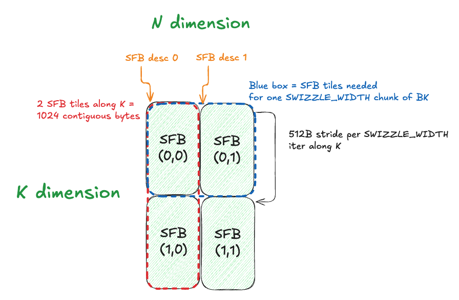
MMA_N=256,MMA_K=32, we will be using a (logical) 256x1 strip of scale factors per MMA. This is arranged as 8 32x1 strips of TMEM, which we select usingSFB_IDas described previously. However, the first two 128x1 strips that compose the 256x1 strip have a stride between them. This was actually annoying and difficult to debug and figure out, so here is a diagram to help visualize it:
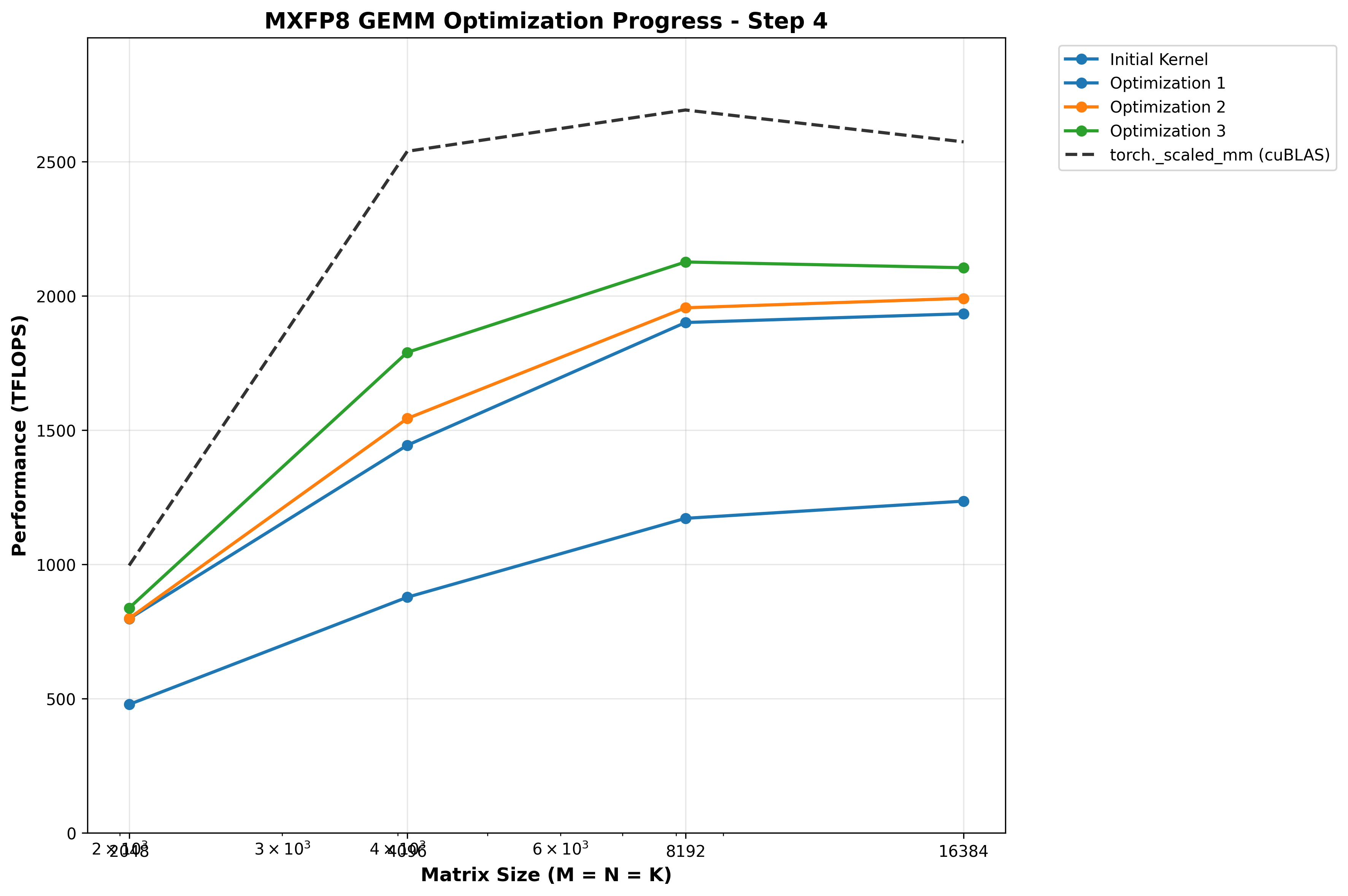
Benchmarks
| Matrix Size (M×K×N) | Custom Kernel | torch._scaled_mm | Speedup |
|---|---|---|---|
| 2048×2048×2048 | 837.55 TFLOPS | 996.05 TFLOPS | 0.84x |
| 4096×4096×4096 | 1789.57 TFLOPS | 2538.40 TFLOPS | 0.70x |
| 8192×8192×8192 | 2126.22 TFLOPS | 2691.93 TFLOPS | 0.79x |
| 16384×16384×16384 | 2104.80 TFLOPS | 2571.48 TFLOPS | 0.82x |
Optimization 4: TMA multicast SFB to both CTAs
One simple optimization we haven’t done this is TMA multicasting for SFB: as mentioned previously, both CTAs need the same replicated SFB for the full BN dimension. Rather than do duplicate global loads, we can use TMA multicasting to load on CTA 0 then broadcast to CTA 1 over higher bandwidth DSMEM. We just need to pass a ctaMask and add the .multicast::cluster modififer to the cp.async.bulk.tensor instruction:
    constexpr uint16_t cta_mask = 0b11;
    asm volatile(
-        "cp.async.bulk.tensor.4d.shared::cluster.global.mbarrier::complete_tx::bytes.cta_group::2 "
+        "cp.async.bulk.tensor.4d.shared::cluster.global.mbarrier::complete_tx::bytes.multicast::cluster.cta_group::2 "
-        "[%0], [%1, {%2, %3, %4, %5}], [%6];"
+        "[%0], [%1, {%2, %3, %4, %5}], [%6], %7;"
        :
        :
        "r"(dst_shmem),
        "l"(tensor_map_ptr),
        "r"(offset_x),
        "r"(offset_y),
        "r"(offset_z),
        "r"(offset_w),
        "r"(mbar_addr),
+       "h"(cta_mask)
        : "memory"
    );
(and be sure to ONLY call it from one CTA in our producer!):
            // sfb tiles are duplicated for all BN on both ctas, so cta 1 multicasts to both
            if (cta_rank == 1) {
                cp_async_bulk_tensor_4d_global_to_shared_multicast(
                    SFB_smem,
                    reinterpret_cast<const uint64_t*>(sfb_map),
                    0,
                    0,
                    (uint32_t)(global_k_off/32/4),
                    (uint32_t)(global_n_off_sfb/128),
                    smem_full_mbar_addrs[tma_smem_buf]
                );
            }
Benchmarks
| Matrix Size (M×K×N) | Custom Kernel | torch._scaled_mm | Speedup |
|---|---|---|---|
| 2048×2048×2048 | 802.50 TFLOPS | 996.05 TFLOPS | 0.81x |
| 4096×4096×4096 | 1789.57 TFLOPS | 2538.40 TFLOPS | 0.70x |
| 8192×8192×8192 | 2134.28 TFLOPS | 2691.93 TFLOPS | 0.79x |
| 16384×16384×16384 | 2143.80 TFLOPS | 2571.48 TFLOPS | 0.83x |
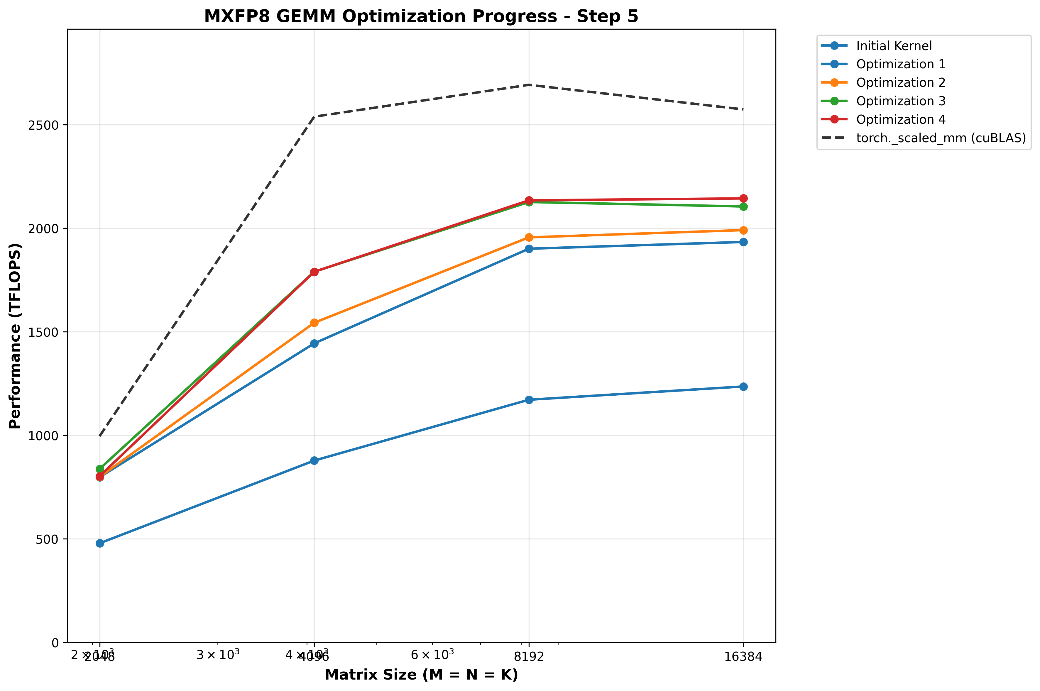
Interestingly, this HURTS performance for M=N=K=2048, is neutral for 4096, and helps larger shapes.
(We will revisit this later!)
Optimization 5: Avoid warp stalling caused by dynamic indexing into arrays
Profiling the kernel with NCU, we see a few instances of long scoreboard warp stalls:
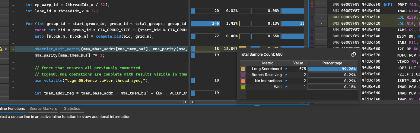
These occur when some register dependency is unmet for the next instruction (i.e., global load to register not yet completed, next instruction operating on that data cannot execute yet).
After consulting the oracles in GPU Mode discord, I was reminded of something I read long ago in PMPP and had forgotten: if allocate an array of registers, then dynamically index into that array, the compiler will instead store the array in local memory - which resides in global memory, which is orders of magnitude lower bandwith and higher latency than register memory. Thus, the way I am using runtime variables to index into the array of mbarriers or parity bits here will of course incur a sizeable performance penalty!
We need to refactor to use static indexing patterns that can be known at compile time:
For example:
        if (mma_tmem_buf == 0) {
            mbarrier_wait_parity(mma_mbar_addr + 0 * MBAR_SIZE, mma_parity[0]);
            mma_parity[0] ^= 1;
        } else {
            mbarrier_wait_parity(mma_mbar_addr + 1 * MBAR_SIZE, mma_parity[1]);
            mma_parity[1] ^= 1;
        }
Benchmarks
Doing this simple refactor to use static indexing yields huge gains for small and medium shapes, up to a whopping 17% increase in TFLOPs/sec for M=N=K=4096! I also confirmed via NCU that no more LDL (load local memory) SASS instructions existed anymore.
| Matrix Size (M×K×N) | Custom Kernel | torch._scaled_mm | Speedup |
|---|---|---|---|
| 2048×2048×2048 | 883.01 TFLOPS | 996.05 TFLOPS | 0.89x |
| 4096×4096×4096 | 2199.16 TFLOPS | 2538.40 TFLOPS | 0.87x |
| 8192×8192×8192 | 2370.29 TFLOPS | 2691.93 TFLOPS | 0.88x |
| 16384×16384×16384 | 2181.83 TFLOPS | 2571.48 TFLOPS | 0.85x |
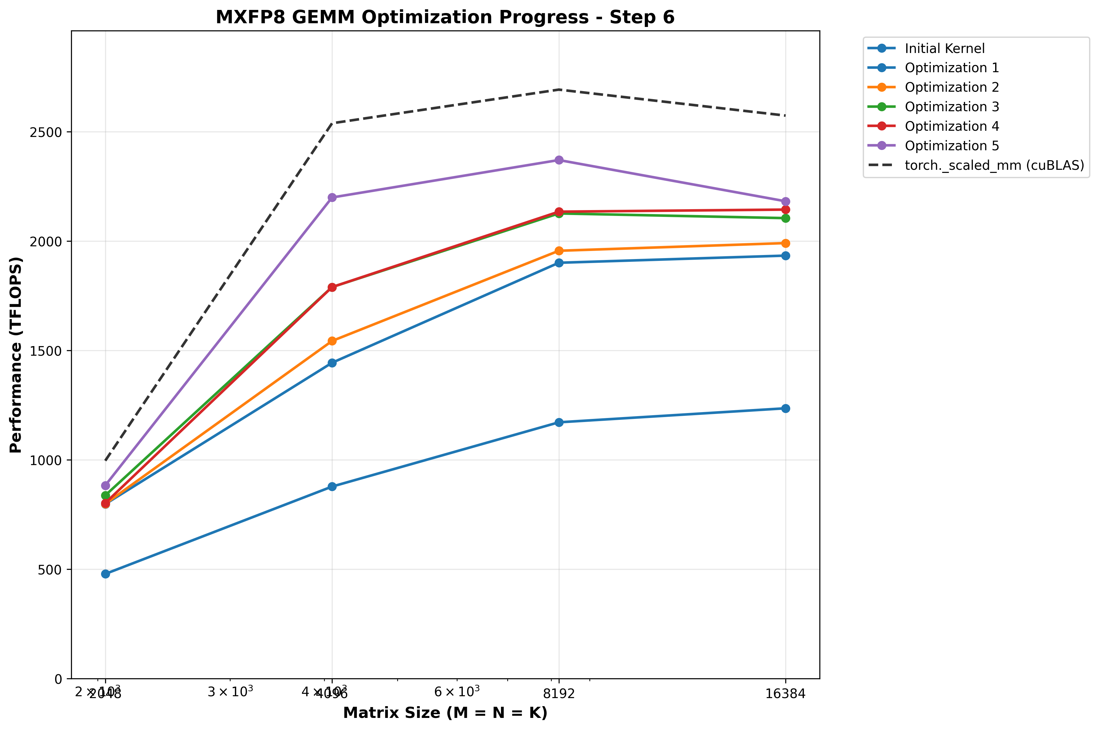
Optimization 6: Hilbert curve scheduling to improve cache utilization
Up until this point, we have been doing a simple grid strided loop over the output matrix. Each pair of SMs cooperatively computes a 256x256 tile of output using 2 CTA MMA, then we iterate by num_groups (NUM_SMS//CTA_GROUP_SIZE, where CTA_GROUP_SIZE=2 for the 2CTA MMA).
However, this leads to poor cache utilization, because the A/B/SFA/SFB tiles used by one output tile are usually totally different than the previous output tile computed on this SM!
There are different block scheduling strategies that try to more intelligently select which output tile a given thread block should compute next, to re-use A/B tiles that are (hopefully) still in the L2 cache. I decided to try using a Hilbert curve as Pranjal did in his WGMMA based BF16 GEMM blog for Hopper.
The Hilbert curve maps 1D block IDs to to 2D coordinates while preserving spatial locality - specifically, it ensures sequential blocks have Manhattan distance <= 1 (meaning sequential blocks are either on the same row, same column, or diagonally adjacent).
The formula used to implement this 1D index -> 2D coordinate mapping with the Hilbert curve involves some dense rotation/reflection math implemented with bitwise operations, that I honestly found hard to parse and didn’t want to devote too much time to the curve’s mathematical formula, which is less interesting to me than the systems level details here. Instead I focused on converting it to operate on the granularity of 2CTA group IDs, instead of individual CTA IDs.
__device__ __forceinline__ std::pair<int, int> compute_bid_hilbert(int bid, int grid_m, int grid_n) {
    constexpr int CTA_GROUP_SIZE = 2;
    const int group_id = bid / CTA_GROUP_SIZE;

    // Square grid so we can use either grid_m or grid_n
    int hilbert_size = grid_m;

    // Map group ID to 2D coordinates using Hilbert curve
    // This ensures groups with consecutive IDs are spatially close
    int group_m, group_n;
    hilbert_index_to_xy(hilbert_size, group_id, &group_n, &group_m);

    // Convert group coordinates back to individual block coordinates
    // Each group spans CTA_GROUP_SIZE blocks vertically (stacked CTAs)
    const int base_block_m = group_m * CTA_GROUP_SIZE;
    const int block_n = group_n;
    const int block_m = base_block_m + (bid % CTA_GROUP_SIZE);

    return {block_m, block_n};
}
The Hilbert curve has some important constraints:
- Grid dims must be a power of 2
- Grid must be square
Therefore, we can use templating and update our launcher to conditionally use Hilbert curve scheduling for USE_HILBERT template initialization when these conditions are true, but default back to static scheduling otherwise.
Benchmarks
First let’s measure L2 cache hit rate to validate the Hilbert curve is working. Running NCU for M=N=K=8192, a larger shape which in theory should benefit more from caching:
ncu --section MemoryWorkloadAnalysis --target-processes all --kernel-name regex:gemm python benchmark.py
Before:
    Section: Memory Workload Analysis
    -------------------------------------- ----------- ------------
    Metric Name                            Metric Unit Metric Value
    -------------------------------------- ----------- ------------
    Local Memory Spilling Requests                                0
    Local Memory Spilling Request Overhead           %      no data
    Memory Throughput                          Tbyte/s         1.59
    Mem Busy                                         %        46.16
    Max Bandwidth                                    %        59.80
    L1/TEX Hit Rate                                  %        51.22
    L2 Persisting Size                           Mbyte        24.87
    L2 Compression Success Rate                      %            0
    L2 Compression Ratio                             %            0
    L2 Compression Input Sectors                sector      8390485
    L2 Hit Rate                                      %        72.00
    Mem Pipes Busy                                   %        81.70
    -------------------------------------- ----------- ------------
After:
    -------------------------------------- ----------- ------------
    Metric Name                            Metric Unit Metric Value
    -------------------------------------- ----------- ------------
    Local Memory Spilling Requests                                0
    Local Memory Spilling Request Overhead           %      no data
    Memory Throughput                          Gbyte/s       903.27
    Mem Busy                                         %        43.12
    Max Bandwidth                                    %        61.49
    L1/TEX Hit Rate                                  %        52.60
    L2 Persisting Size                           Mbyte        24.87
    L2 Compression Success Rate                      %            0
    L2 Compression Ratio                             %            0
    L2 Compression Input Sectors                sector      8393148
    L2 Hit Rate                                      %        85.67
    Mem Pipes Busy                                   %        84.03
    -------------------------------------- ----------- ------------
We see the L2 hit rate increase from 72% to 85%, a huge win! Notably, the L1 hit rate is roughly the same at ~52%. I suspect this is because L2 size (126MB) is much bigger than L1 (256kb of SMEM+L1), so the previous A/B/SFA/SFB tiles have probably been evicted from L1 but still are present in L2.
Benchmarks show the Hilbert curve yields huge gains for large shapes (M=N=K >= 8192) is net neutral for small and medium shapes:
| Matrix Size (M×K×N) | Custom Kernel | torch._scaled_mm | Speedup |
|---|---|---|---|
| 2048×2048×2048 | 881.56 TFLOPS | 996.05 TFLOPS | 0.89x |
| 4096×4096×4096 | 2159.36 TFLOPS | 2538.40 TFLOPS | 0.85x |
| 8192×8192×8192 | 2502.71 TFLOPS | 2691.93 TFLOPS | 0.93x |
| 16384×16384×16384 | 2412.20 TFLOPS | 2571.48 TFLOPS | 0.94x |
This makes sense, since for larger shapes we actually have a reasonably large grid of 256x256 output tiles to compute (e.g. 32x32 for 8192), which should benefit from caching more than a small problem size, with say a 8x8 grid, which actually is only 64 tiles. This is fewer than the 148 SMs on B200, so each SM that does any work would only compute one tile, so cache-aware scheduling will bring no benefit!
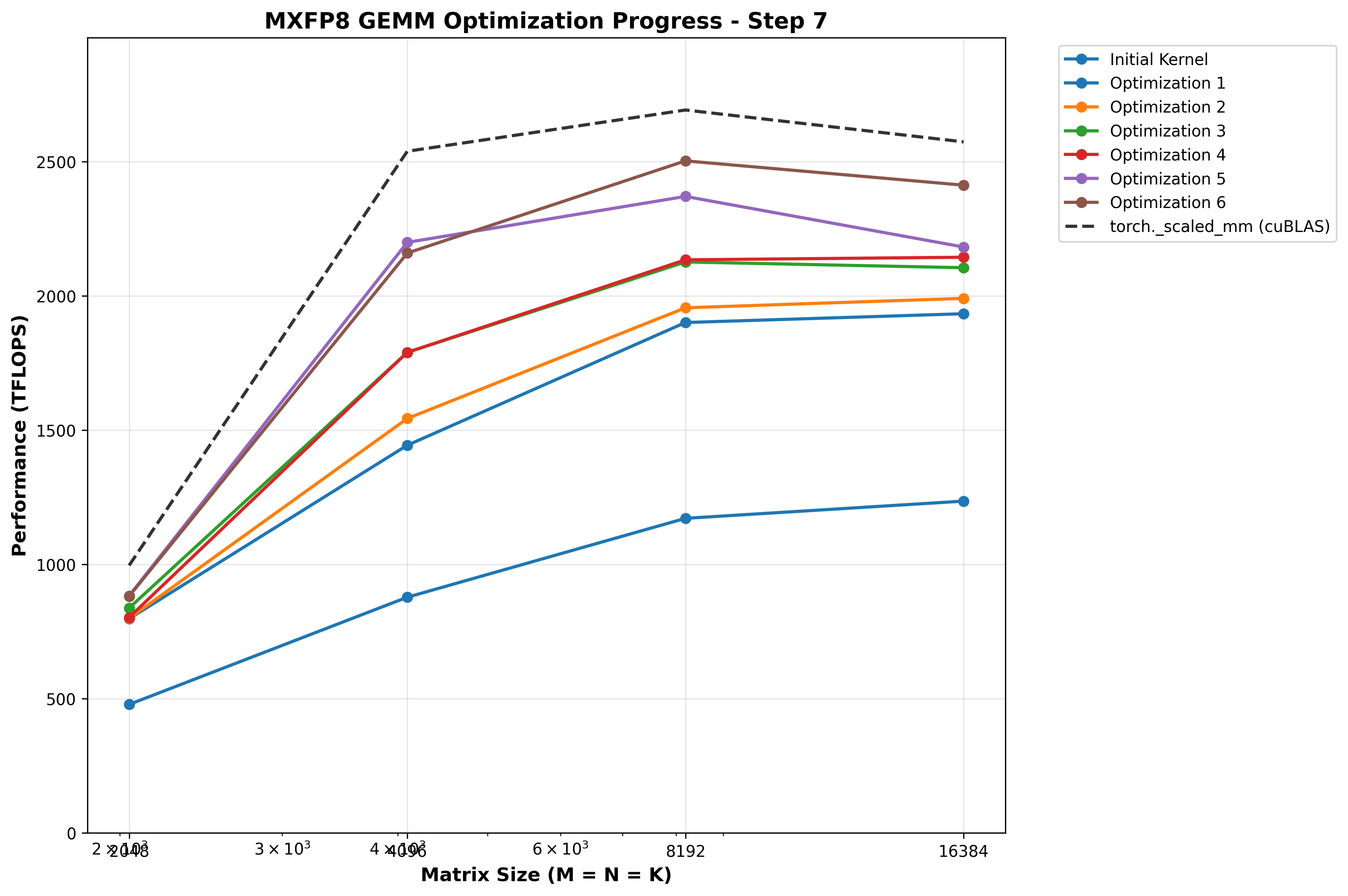
Optimization 7: Use L1::no_allocate modifier global stores
One other known optimization for global stores that we don’t intend to read again is to modify the cache hinting used in the instruction; that is, we shouldn’t waste time and space caching data we don’t ever intend to read! This is not only a waste of time, but also actively harmful because we may evict data from the cache that we DO need to re-use.
Consulting the PTX docs for st.global, we see these options for caching behavior:
.level1::eviction_priority = { .L1::evict_normal, .L1::evict_unchanged,
                               .L1::evict_first, .L1::evict_last, .L1::no_allocate };
.level2::eviction_priority = { .L2::evict_normal, .L2::evict_first, .L2::evict_last };
One common concept in GPU or CPU performance is “data written recently is often read soon,” so this is the only explanation I can come up with for why data written to global memory is cached in our L1 by default, which has precious and limited storage.
Benchmarks
Benchmarks show a slight performance boost for larger shapes, which are approaching cuBLAS performance now:
| Matrix Size (M×K×N) | Custom Kernel | torch._scaled_mm | Speedup |
|---|---|---|---|
| 2048×2048×2048 | 885.93 TFLOPS | 996.05 TFLOPS | 0.89x |
| 4096×4096×4096 | 2201.42 TFLOPS | 2538.40 TFLOPS | 0.87x |
| 8192×8192×8192 | 2537.46 TFLOPS | 2691.93 TFLOPS | 0.94x |
| 16384×16384×16384 | 2432.80 TFLOPS | 2571.48 TFLOPS | 0.95x |
Interestingly, when I tried playing with L2 cache hint, I always got worse results versus just leaving it unset. This confuses me, since intuitively it would seem that we should evict the output tile we’re storing to global memory from L2 as soon as possible, since we have no intent to ever read it. The evict-first policy would be best, but there’s actually a substantial performance drop when we use it.
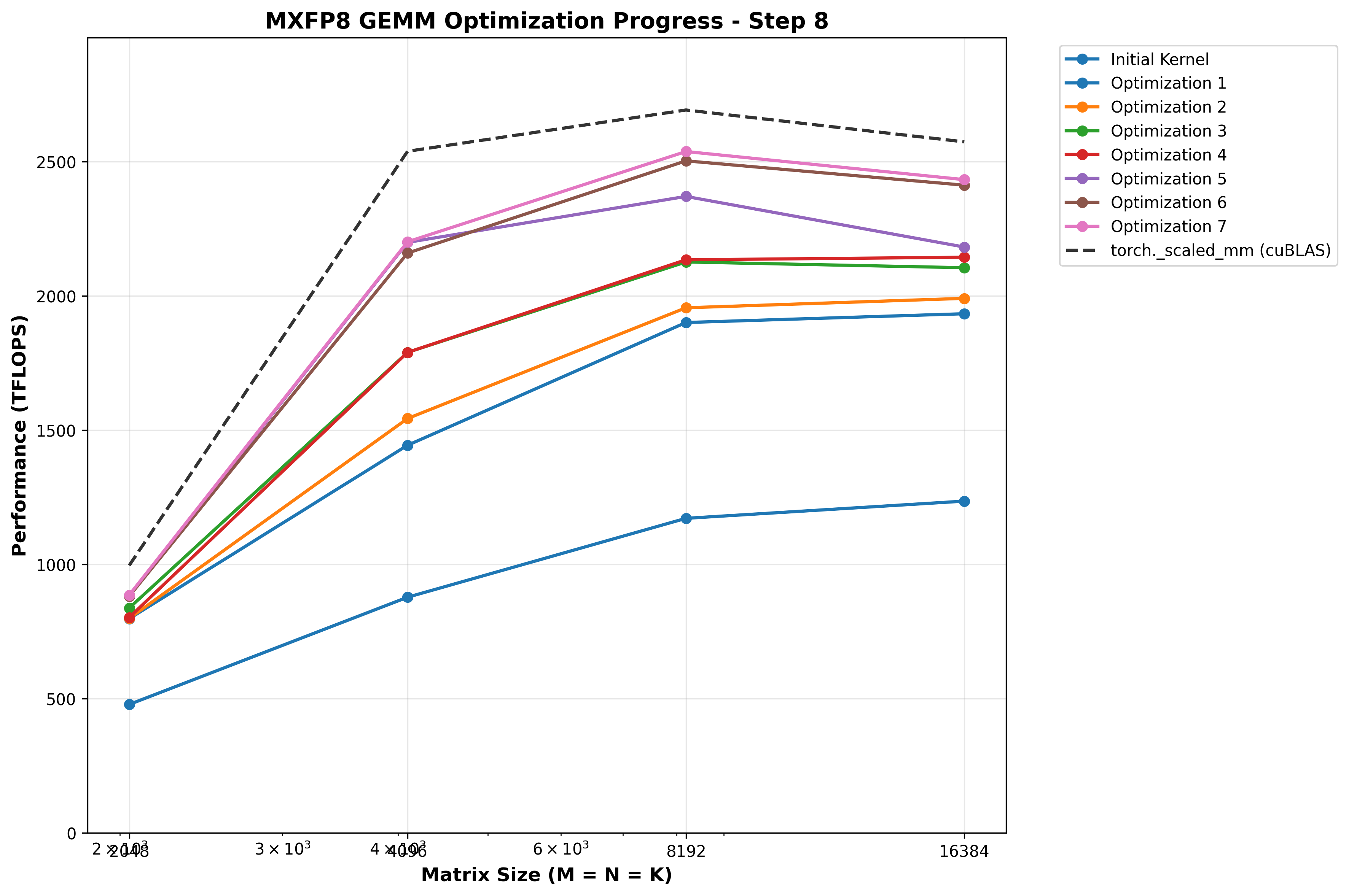
Optimization 8: Use Hilbert curve only for M/N/K >= 8192
At this point since Hilbert curve was net neutral for shapes smaller than 8192, I updated template initialization and dispatching to only use the Hilbert curve scheduling when M=N=K >= 8192 as it may be adding unnecessary overhead for smaller shapes. To my surprise, when combined with the L1::no_alloc change to global stores above, peformance for M=N=K=2048 hits 98% of cuBLAS!
Benchmarks
| Matrix Size (M×K×N) | Custom Kernel | torch._scaled_mm | Speedup |
|---|---|---|---|
| 2048×2048×2048 | 979.69 TFLOPS | 996.05 TFLOPS | 0.98x |
| 4096×4096×4096 | 2206.51 TFLOPS | 2538.40 TFLOPS | 0.87x |
| 8192×8192×8192 | 2526.08 TFLOPS | 2691.93 TFLOPS | 0.94x |
| 16384×16384×16384 | 2447.84 TFLOPS | 2571.48 TFLOPS | 0.95x |
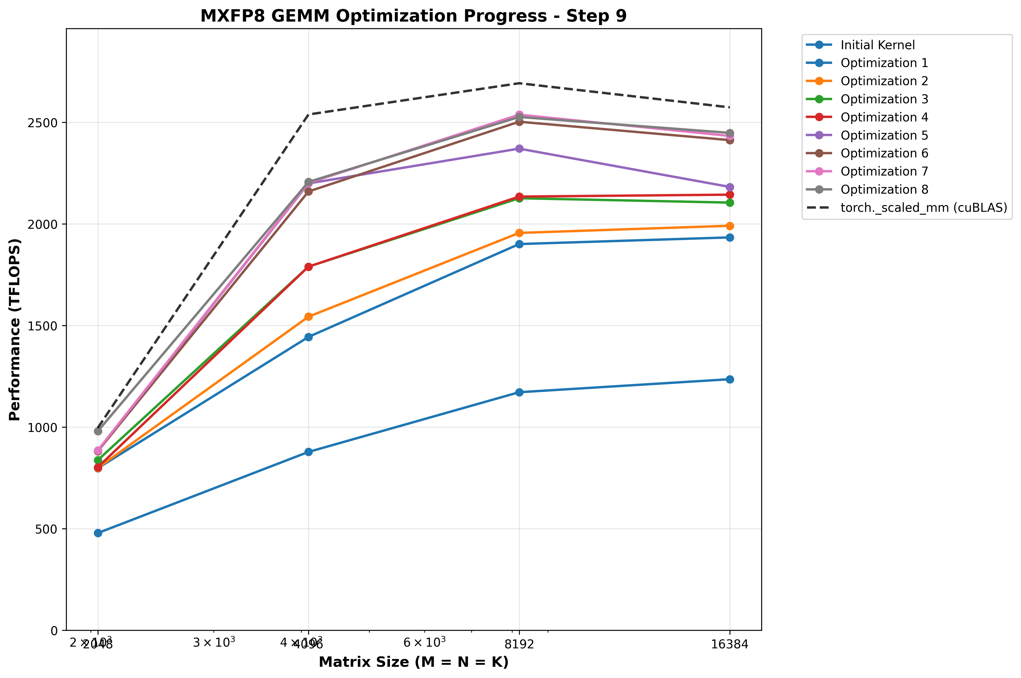
Optimization 9: New DeepGEMM inspired epilogue strategy: TMEM -> REG -> pipelined TMA stores with manual swizzle in SMEM
At this point, I profiled with NCU again, trying to and found something interesting in the epilogue:
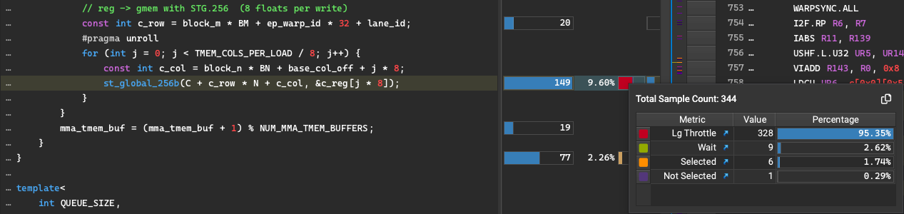
Warp stalls with Lg-throttle - this seems to indicate the LSU pipeline is full, our raw STG based storage strategy is overwhelming the hardware’s ability to process them quickly enough. This is leading to warp stalls when we try to issue the STG instruction. In some ways this is a good signal - it means the prior parts of the pipeline (producer -> consumer) are operating efficiently enough to give the epilogue more data to process than it can handle! How can we optimize this further though?
For this, I began researching other high performance sm100 GEMM implementations, and in the DeepGEMM sm100 FP8 GEMM epilogue found this interesting strategy. Rather than do straight up STG, they do the following:
- Allocate a small section of SMEM as a TMA store staging area
- 3 stage pipeline:
- TMEM -> register load
- Register -> SMEM write with manual swizzle (swizzle width chosen at dispatch time based on shapes)
- TMA shared -> global store with that swizzle encoded
- Double buffer the SMEM staging area so we can overlap TMA reading SMEM with generic proxy writing to SMEM, and always have at least 1 TMA store in flight during the loop.
Notably, TMA does NOT use the LSU for global stores, it is a separate hardware unit dedicated to efficient shared <-> global memory movement.
This strategy was surprising to me at first; I had considered using TMA stores but decided against it, at least initially due to:
- The
BMxBNoutput tile in SMEM would substantially reduce remaining SMEM for the producer queue.BMxBN=32768, which is a sizable chunk of our 227k of SMEM per SM. We would probably lose one or more queue stages, limiting our prefetching and steady state overlap. - The extra copy being incurred (to SMEM, which has much higher bandwidth and lower latency than GMEM, but still)
- The bank conflicts that would arise, and would require complex manual swizzling math to resolve or minimize (which sometimes ends up being net neutral or negative due to the additional ALU overhead in those calculations!)
However, I had not considered this pipelined approach, where we only store a fraction of the full BMxBN tile in SMEM at a given time, and pipeline the “TMEM -> registers” stage with the “registers -> SMEM then issue TMA store” stage. This means we would lose at most one queue stage, rather than at least one queue stage.
Since the DeepGEMM team got it to work well, I decided to give it a shot as well.
I also use a modified the design to account for the fact we have 128 overlapping accumulator TMEM columns, that we need to read ASAP to unblock the next MMA. So in my design, rather than pipeline 4 floats at time from TMEM -> registers -> SMEM, I read the entire 128 columns from TMEM into registers, unblock the next MMA immediately, then iterate through the registers, writing them in 16B chunks to a 128B swizzle layout in SMEM manually, then issuing a TMA store.
The design is slightly modified - at this point I choose to read the entire 128 TMEM columns in one tcgen05.ld so I can unblock the next MMA asap. In DeepGEMM, they pipeline 4 column TMEM loads -> 4 float SMEM writes. (We will revisit this later!)
Our process_epilogue_chunk_tma helper, which processes one 128 column chunk of TMEM, looks something like this (simplified for brevity):
    // TMA store path: reg -> smem -> TMA -> gmem
    constexpr int TMA_BUFFER_COLS = SWIZZLE_BYTES / sizeof(float);    // 128B swizzle / 4 = 32 cols
    constexpr int NUM_TMA_CHUNKS = COLS / TMA_STORE_COLS;             // 128 TMEM cols / 32 = 4 chunks
    constexpr int NUM_SUB_CHUNKS = TMA_STORE_COLS / TMA_BUFFER_COLS;  // 32 / 32 = 1 subchunks per chunk
    constexpr int BUFFER_SIZE = BM * TMA_BUFFER_COLS * sizeof(float); // 128*32*4=16384 bytes
    const int smem_row = ep_warp_id * 32 + lane_id;
    constexpr int smem_stride = TMA_BUFFER_COLS;

    #pragma unroll
    for (int chunk = 0; chunk < NUM_TMA_CHUNKS; chunk++) {
        #pragma unroll
        for (int sub = 0; sub < NUM_SUB_CHUNKS; sub++) {
            // we issue 1 tma store per sub chunk (rotating between them).
            // wait until one finishes (if issued by the same thread like here,
            // they finish in same order as issued, so we know the next smem
            // buffer is the one that will be be ready for re-use)
            if (ep_warp_id == 0)
                asm volatile("cp.async.bulk.wait_group.read %0;" :: "n"(NUM_SUB_CHUNKS-1) : "memory"
);
            warpgroup_sync();

            uint32_t buffer_addr = smem_tma_store_addr + sub * BUFFER_SIZE;

            // write 4 byte chunks from registers to SMEM with manual 128B swizzle with 16B atoms
            #pragma unroll
            for (int j = 0; j < TMA_BUFFER_COLS / 4; j++) {
                const int reg_col = chunk * TMA_STORE_COLS + sub * TMA_BUFFER_COLS + j * 4;
                const int smem_col = j * 4;
                st_shared_fp32_swizzle_128b<4>(
                    buffer_addr,
                    smem_row,
                    smem_col,
                    smem_stride,
                    &c_reg[reg_col]
                );
            }

            // ensure writes visible to tma
            warpgroup_sync();
            asm volatile("fence.proxy.async.shared::cta;");

            // issue TMA store
            if (threadIdx_x == epilogue_master_thread)
            {
                const int c_row = block_m * BM;
                const int c_col = block_n * BN + col_offset + chunk * TMA_STORE_COLS + sub * TMA_BUFFER_COLS;

                cp_async_bulk_tensor_2d_shared_to_global(c_map_ptr, c_col, c_row, buffer_addr);
                asm volatile("cp.async.bulk.commit_group;");
            }
        }
The manually swizzled write to SMEM (128B swizzle with 16B chunks) looks like this:
template <int VECTOR_SIZE>
__device__ __forceinline__ void st_shared_fp32_swizzle_128b(
    uint32_t smem_base_addr,
    int row,
    int col,
    int stride,
    const float reg[VECTOR_SIZE])
{
    static_assert(VECTOR_SIZE == 1 || VECTOR_SIZE == 2 || VECTOR_SIZE == 4 || VECTOR_SIZE == 8,
                  "VECTOR_SIZE must be 1, 2, 4, or 8");

    // swizzle: swizzle 16B chunks within 128B span
    // formula: col ^= row % (128B / 16B) = row % 8

    int chunk_idx = col / 4; // divide by 4 since this is fp32 data, so 16B/4B per elem = 4
    int chunk_offset = col % 4;
    int swizzled_chunk = chunk_idx ^ (row & 7); // row & 7 == row % 8
    int col_swizzled = swizzled_chunk * 4 + chunk_offset;

    uint32_t addr = smem_base_addr + row * stride * sizeof(float) + col_swizzled * sizeof(float);
    st_shared_fp32<VECTOR_SIZE>(addr, reg);
}
Benchmarks
After reaching some volcanic levels of anger, I managed to finally get it working and the results show +1% TFLOPs/sec for large shapes (M=N=K >= 8192) and slowdown for smaller shapes.
| Matrix Size (M×K×N) | Custom Kernel | torch._scaled_mm | Speedup |
|---|---|---|---|
| 2048×2048×2048 | 884.47 TFLOPS | 996.05 TFLOPS | 0.89x |
| 4096×4096×4096 | 2202.55 TFLOPS | 2538.40 TFLOPS | 0.87x |
| 8192×8192×8192 | 2550.27 TFLOPS | 2691.93 TFLOPS | 0.95x |
| 16384×16384×16384 | 2478.36 TFLOPS | 2571.48 TFLOPS | 0.96x |
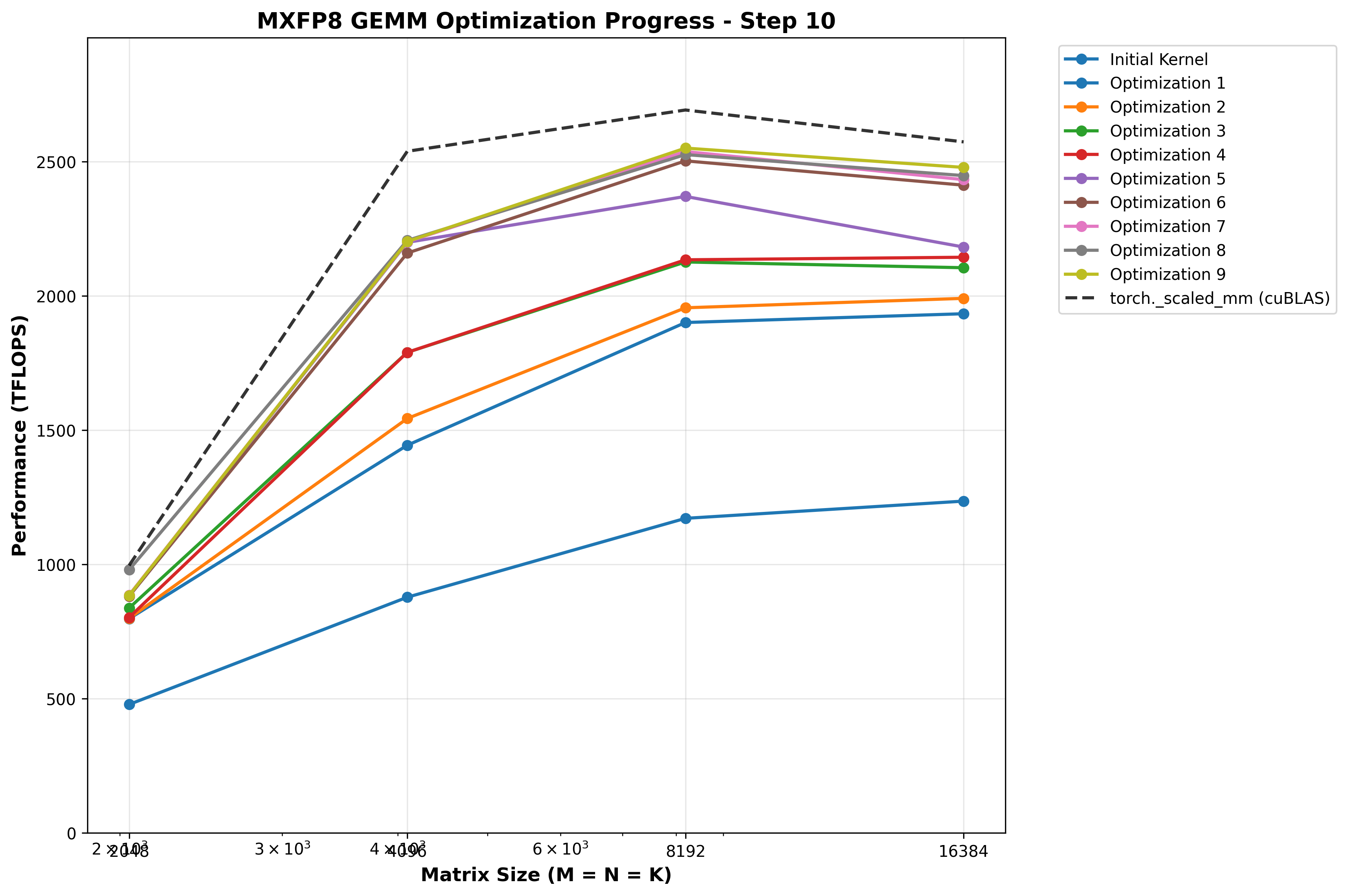
Now if only we can combine the benefits of STG for smaller shapes and TMA for larger shapes…
Optimization 10: Heuristic based epilogue strategy
Our final optimization is just templating the epilogue to optionally support both direct global stores with st.global.L1::no_allocate.v8.f32, or the pipelined TMA stores. Then in the launcher, we can just use the heuristic we found in our microbenchmarks earlier to only use the TMA store strategy when M=N=K >= 8192.
In addition, I did various micro-optimizations to address some structural inefficiencies in the C++ code itself (recomputing variables in the inner loop that could be hoisted outside the loop; using bitwise ops instead of modulo or division, etc.).
Benchmarks
This unified kernel produces our best results:
| Matrix Size (M×K×N) | Custom Kernel | torch._scaled_mm | Speedup |
|---|---|---|---|
| 2048×2048×2048 | 986.90 TFLOPS | 996.05 TFLOPS | 0.99x |
| 4096×4096×4096 | 2200.29 TFLOPS | 2538.40 TFLOPS | 0.87x |
| 8192×8192×8192 | 2599.07 TFLOPS | 2691.93 TFLOPS | 0.97x |
| 16384×16384×16384 | 2487.72 TFLOPS | 2571.48 TFLOPS | 0.97x |
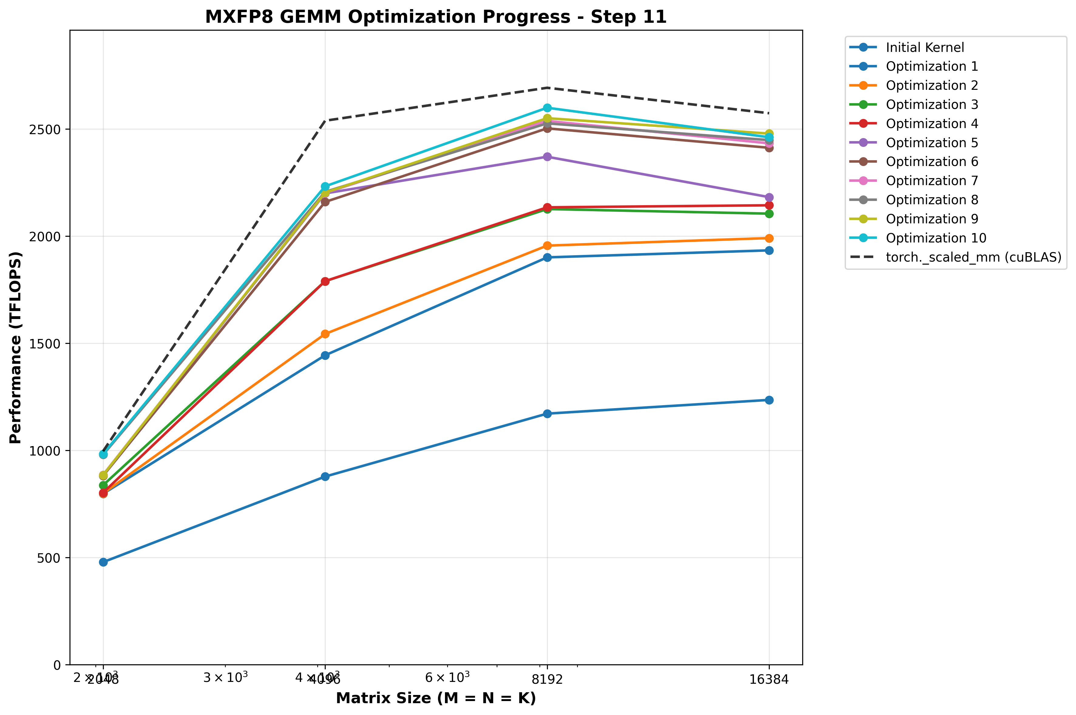
Optimization 11: More granular TMEM overlapping
Up until this point, we have stuck with our simple strategy of overlapping 128 columns of TMEM for our accumulators. However, as noted previously, this is actually more than we need to overlap. Intuitively, it would seem that overlapping the minimal possible columns would be best, as we need to load fewer bytes from TMEM to registers in order to unblock the next MMA.
First, let’s recalculate how many total columns of TMEM we need for A/B/SFA/SFB using BN=256, BK=256:
Given:
- A tile [BM,BK] = [128,256]
- B tile [BN,BK] = [256,256]
SFA/SFB TMEM
- SFA [BM/128, BK/32/4, 32, 16] = [1, 2, 32, 16] = two 512 byte sfs, each a 32x4 chunk of TMEM (32x16B) = 32x8 TMEM requirement
- SFB [BN/128, BK/32/4, 32, 16] = [2, 2, 32, 16] = four 512 byte sfs, each a 32x4 chunk of TMEM (32x16B) = 32x16 TMEM requirement
So thats 8+16=24 columns of TMEM per warp zone for SFA/SFB. Add that to our two BN=256 accumulators and we get:
256*2 + 24 = 536TMEM columns, 24 more than we have.
How can we support this with more granular overlapping, given the tcgen05.ld shape constraints above? First, let’s try cutting the number of overlap columns in half, which will be more complex but simpler than even more granular overlapping. If this yields perf results, this will provide good evidence that we should continue driving on this path.
With 64 TMEM columns of overlap, our TMEM layout looks like this:
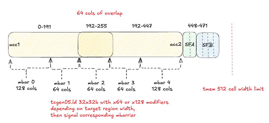
The additional mbarrier synchronizations and imbalanced TMEM regions adds additional complexity to the code, but in the end we get it working!
Benchmarks
Sadly, the benchmarks show no measurable impact - if anything, they appear slightly worse, although with small differences sometimes jitter between benchmark runs makes it difficult to know precisely.
| Matrix Size (M×K×N) | Custom Kernel | torch._scaled_mm | Speedup |
|---|---|---|---|
| 2048×2048×2048 | 981.48 TFLOPS | 996.05 TFLOPS | 0.99x |
| 4096×4096×4096 | 2202.55 TFLOPS | 2538.40 TFLOPS | 0.87x |
| 8192×8192×8192 | 2550.27 TFLOPS | 2691.93 TFLOPS | 0.95x |
| 16384×16384×16384 | 2425.23 TFLOPS | 2571.48 TFLOPS | 0.94x |
Conclusion
Wow, this was quite the journey! If you read this far, thank you so much for fully engaging with the material, this was a labor of love and it brings me joy to share it with like minded people who are interested in these low level ML performance details, I hope you got a lot out of it :)
For any curious souls out there up for a challenge, try taking a crack at optimizing the M=N=K=4096 shape, which has remained stubbornly at 87% of cUBLAS performance, despite my addressing things found with NCU like warp stalls on global stores, etc. I wonder if cuBLAS uses a fundamentally different design, block scheduling strategy, or if I simply have some inefficiencies in my code that I’ve missed.
For now though, I am tired, and would like to move onto my new curiosity: mastering CuteDSL, which is more pragmatic for my actual day job!